Planar coil and method of making the same

a planar coil and coil technology, applied in the direction of magnets, cores/yokes, magnets, etc., can solve the problems of trapezoidal cross section of the coil and poor electrical properties of the coil, and achieve the effect of avoiding the formation of gaps in the trench

Inactive Publication Date: 2013-02-21
GREDMANN TAIWAN
View PDF0 Cites 0 Cited by
  • Summary
  • Abstract
  • Description
  • Claims
  • Application Information

AI Technical Summary

Benefits of technology

The present invention describes a method for making a planar coil, which involves several steps. These steps include providing a substrate, covering the substrate with a patterned photoresist layer, etching the substrate to form a trench, removing the photoresist layer, applying a barrier, growing a seed layer, covering the predetermined area with an isolative layer, filling up the trench with conductive material, and removing a portion of the isolative layer and the seed layer located above the predetermined area. The method involves using an isolative layer to guide the conductive material and prevent accumulation of the conductive material at the opening of the trench. The technical effect of the invention is to prevent gap formation in the trench and achieve a more complete filling of the trench with conductive material, resulting in improved performance of the planar coil.

Problems solved by technology

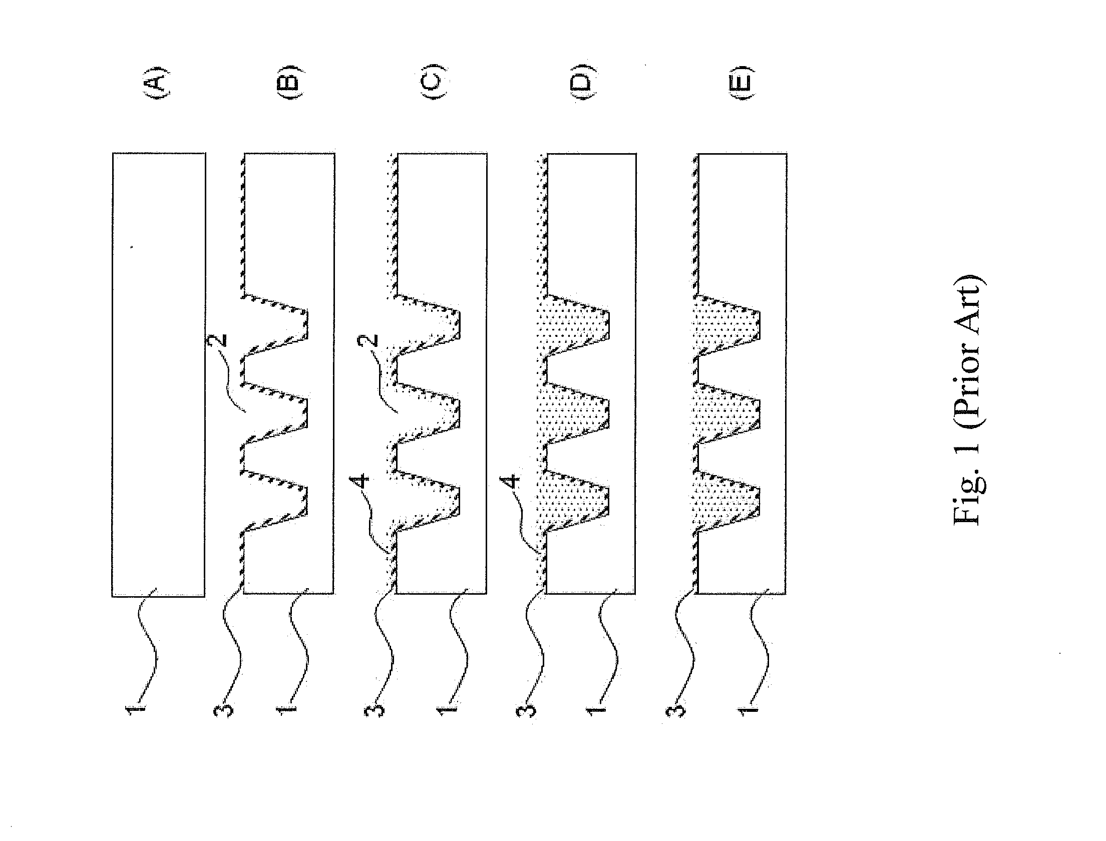
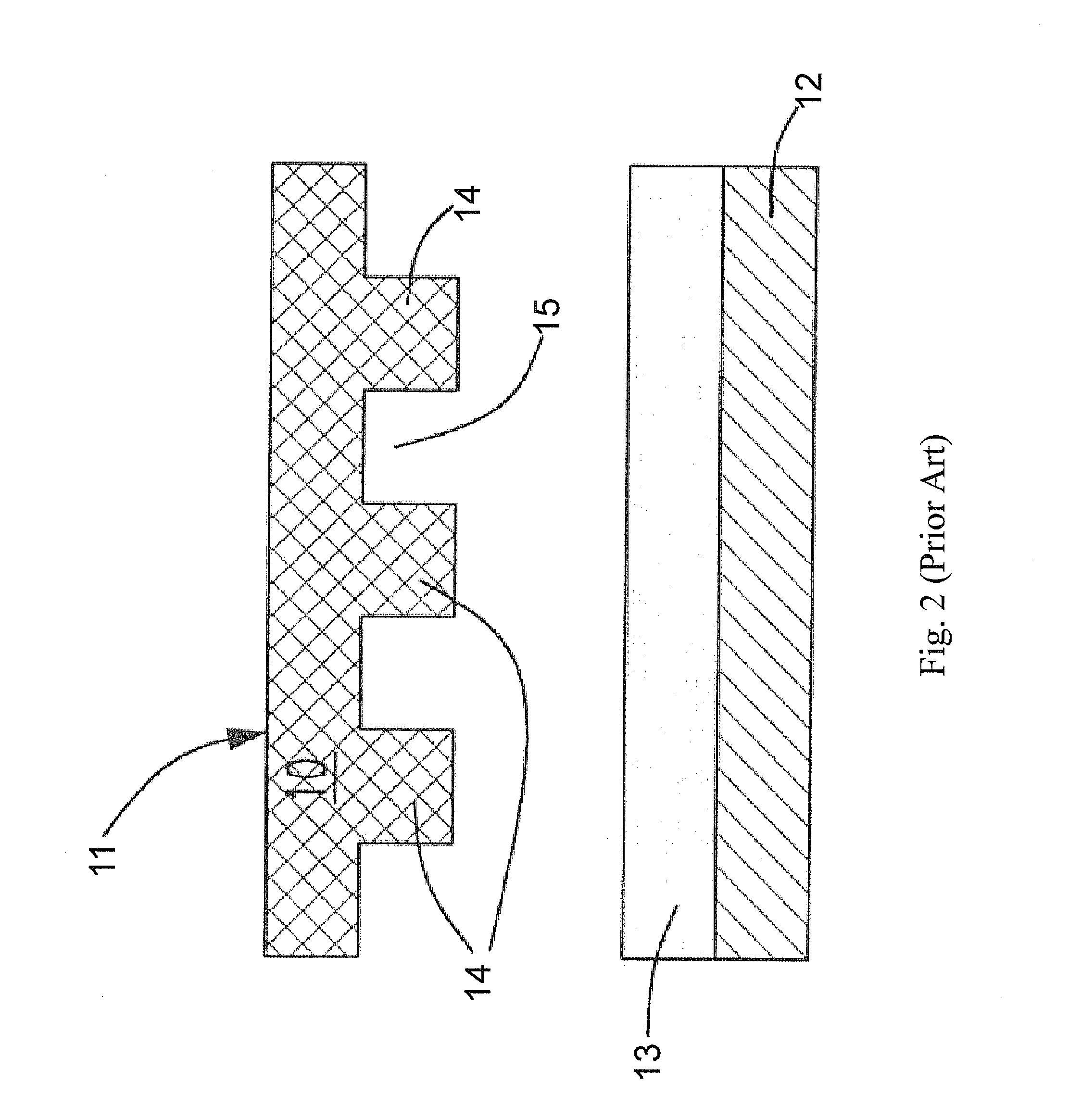
An obvious defect is that the cross section of the coil is trapezoidal.
Usually, gaps are formed in the coil during a cryogenic process or Bosch process while making high aspect ratios of cross section for the planar coil, causing poor electrical properties of the coil.

Method used


Image

  • Planar coil and method of making the same
  • Planar coil and method of making the same
  • Planar coil and method of making the same

Examples


Embodiment Construction

[0043]Please refer to FIGS. 4 to 11. An embodiment is described. FIG. 4 is a top view of a planar coil 110. It has a coil body 105 formed on a substrate 100. In this embodiment, the substrate 100 is a silicon substrate. In order to make illustration of the present invention more comprehensive, a cross section is taken along line AA′ to depict the steps of the invention.

[0044]Please refer to FIG. 5. In the beginning of making the planar coil 110, a patterned photoresist layer 101 is applied on the substrate 100 covering a predetermined area. Later, a number of trenches 102 are formed by etching the substrate at a place outside of the predetermined area, as shown in FIG. 6. In the present invention, deep reactive-ion etching (DRIE) is used for etching. DRIE is a highly anisotropic etching process used to create deep, steep-sided holes and trenches in wafers, with aspect ratios of 20:1 or more. It was developed for micro electromechanical systems (MEMS) which require these features. Th...


PUM

PropertyMeasurementUnit
aspect ratioaaaaaaaaaa
mechanicalaaaaaaaaaa

Abstract

A method of making a planar coil is disclosed in the present invention. First, a substrate having a trench is provided. Then, a barrier and a seed layer are formed on the substrate in sequence. An isolative layer is used for guiding a conductive material to flow into a lower portion of the trench such that accumulation of the conductive material at opening of the trench is prevented before the lower portion of the trench is completely filled up, thereby avoiding gap formation in the trench.

Description

CROSS REFERENCE TO RELATED APPLICATIONS[0001]The present application is a Divisional application of U.S. patent application Ser. No. 12 / 899,836, filed on Oct. 7, 2010.FIELD OF THE INVENTION[0002]The present invention relates to a method for making a planar coil. More particularly, the present invention relates to a method for making a planar coil by micro-electro-mechanical system (MEMS) processes.BACKGROUND OF THE INVENTION[0003]The technology combining micromachining and integrated circuit processes becomes mature. Thus, for many micro-electro-mechanical system (MEMS) devices, microactuators are used to provide driving force and play a key part in operation. So far, electromagnetic microactuators are the main stream because the making processes are quite simple. In general, the electromagnetic microactuators are composed of a magnet and a planar coil. The planar coil can be obtained by integrated circuit processes.[0004]The planar coil is applied to many MEMS devices. A planar coi...

Claims


Application Information

Patent Timeline
Patent Type & Authority Applications(United States)
IPC IPC(8): C25D5/02C25D7/00
CPCH01L21/76H01F5/003H01F41/042Y10T29/49069Y10T29/49071Y10T29/49073Y10T29/49146
Inventor LIN, HUNG YICHEN, MING FA
Owner GREDMANN TAIWAN
Why Eureka
Try Eureka