
Lightweight rerailer

Active Publication Date: 2013-02-21
PENNSY CORP
View PDF2 Cites 15 Cited by
  • Summary
  • Abstract
  • Description
  • Claims
  • Application Information

AI Technical Summary

Benefits of technology

The present invention provides an improved lightweight rerailer for realigning derailed wheel of a railroad vehicle back onto the track. The rerailer is made from lighter weight material with similar or better tensile strength. The load bearing areas of the rerailer are reduced to reduce material usage. The rerailer is configured for easy transportation due to its weight. The rerailer also has an improved construction for handling and transferring stress loads. The cross directional ridges provide sufficient strength to the rerailer structure. The technical effects of the invention include improved efficiency, durability, and reduced material usage for weight reduction.

Problems solved by technology

The derailment of the railroad cars is often a result of uneven loads being carried by the cars, the condition of the track, or other factors.
A common cause of the derailing of railroad cars is due to the cars rocking back and forth on the tracks.
The rocking may cause one or more of the cars, in particular a wheel of the car, to rock off of the rail of the track.
Aside from requiring more power and energy to pull the derailed car, there is a risk of danger or injury should the derailed wheel encounter an obstruction that would impede it from continuing to move along in the direction in which it is being pulled by the locomotive.
Even the contact of the derailed wheel with the gravel, ties or other structure has the potential to cause decoupling of the derailed car from other cars.
The prior devices involve considerable installation procedures and are heavy to transport and install.
This makes for difficult lifting and transport of the rerailers from a location to the site of the track location where the vehicle to be rerailed is located.
The current rerailers require costs and difficulty to move and transport.

Method used


Image

  • Lightweight rerailer
  • Lightweight rerailer
  • Lightweight rerailer

Examples


Embodiment Construction

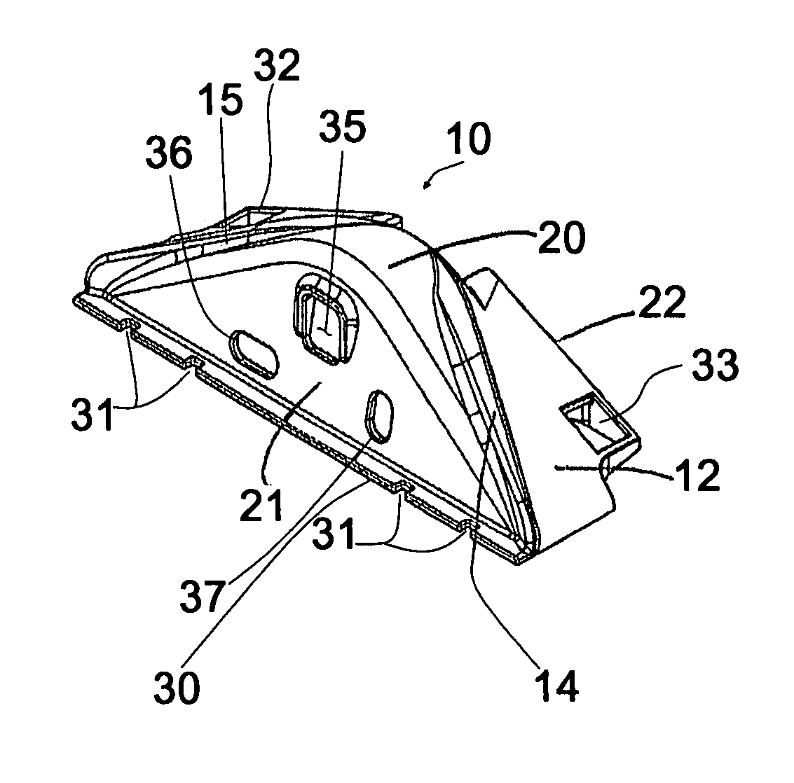
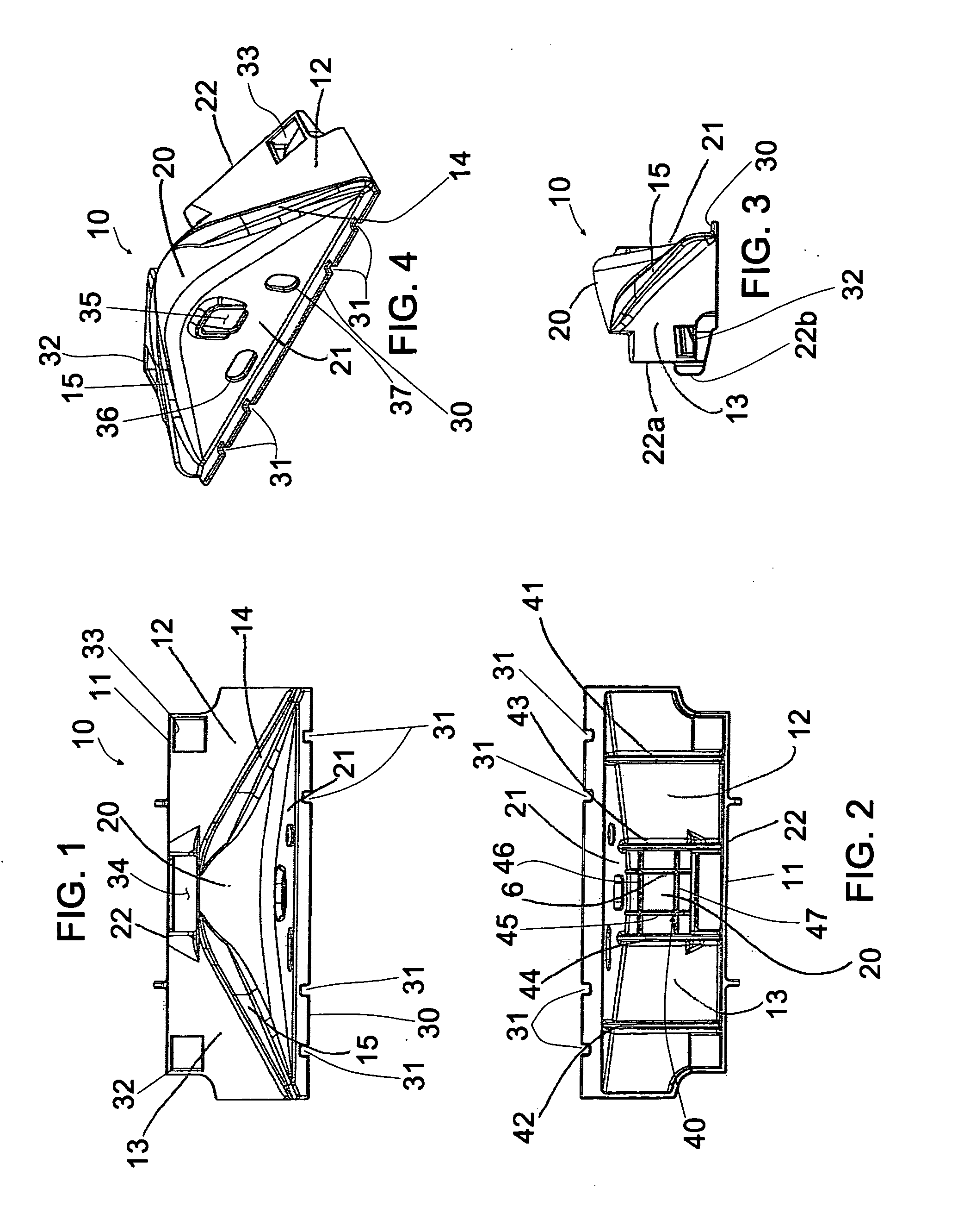
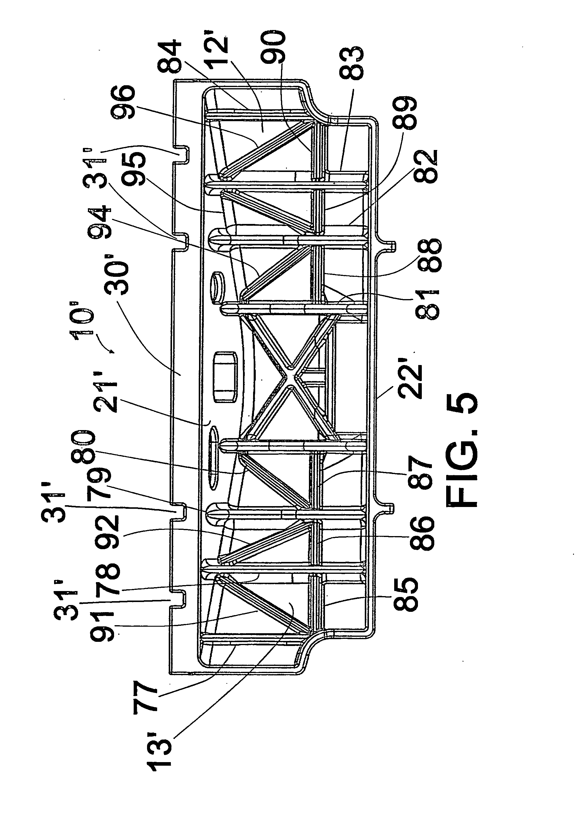
[0042]Rerailer devices are provided in accordance with the invention. According to one embodiment, an improved rerailer is constructed as a ramp style, y-style or permanent style rerailer. One exemplary embodiment of the invention is illustrated in FIGS. 1-4, where a bi-directional, outside rerailer 10 is shown. The bi-directional rerailer 10 illustrated in FIGS. 1-4 is configured as an outside rerailer. FIGS. 10-14 illustrate an inside rerailer. The outside rerailer 10 and inside rerailer 110 preferably may be used in pairs, and positioned on opposite lateral sides of a track rail. The rerailers of the invention, such as, for example, the outside rerailers 10, 110, preferably are sized to accommodate a derailed car wheel, which may be several inches from the rail. The rerailers 10, 110 are also configured for use with optional extenders, not shown, which are designed to be positioned to extend the ramp surface of the rerailers 10, 110 for derailed cars whose derailed wheel is subst...


PUM


Abstract

A rerailer device for rerailing a railway vehicle onto a track, the device including a body with a ramp adapted to support a wheel of a railway vehicle thereon, a sloped face provided on said body and being configured with a slope that declines in a preferred direction toward the track on which the railway vehicle wheel is to be rerailed, and support means for supporting said sloped surface and railway vehicle wheels thereon, where the support configuration, material or combinations of configurations and materials facilitate lightweight construction.

Description

BACKGROUND OF THE INVENTION[0001]1. Field of the Invention[0002]The present invention relates to improvements in devices that are useful for placing derailed cars and locomotives back onto the track.[0003]2. Brief Description of the Related Art[0004]In the operation of railroads, it is sometimes the case where railroad cars, including locomotives, become derailed as they are moving along the track. The derailment of the railroad cars is often a result of uneven loads being carried by the cars, the condition of the track, or other factors. A common cause of the derailing of railroad cars is due to the cars rocking back and forth on the tracks. The rocking may cause one or more of the cars, in particular a wheel of the car, to rock off of the rail of the track. When a car is off the track, the locomotive that is pulling or pushing the derailed car will usually possess sufficient power to continue to move the car along the track, but with the derailed car wheel or wheels being dragged ...

Claims


Application Information

Patent Timeline
IPC IPC(8): B61K5/00
CPCB61K5/00B61K5/06B61K5/02
Inventor SCHMIDT, MICHAEL J.BROOK, ZACHARY RYANTAVARES, MANUEL
Owner PENNSY CORP
Learn More