
Oil mist separation in gas turbine engines

a gas turbine engine and oil mist technology, applied in the direction of liquid fuel engines, machines/engines, transportation and packaging, etc., can solve the problems of reducing the life of components, affecting the performance of components, and affecting the operation of seals, bearings or cooling passages

Inactive Publication Date: 2013-02-14
ROLLS ROYCE PLC
View PDF14 Cites 9 Cited by
  • Summary
  • Abstract
  • Description
  • Claims
  • Application Information

AI Technical Summary

Benefits of technology

The patent text describes a device that separates oil from a flow of gas in a rotor stage. The device has a tortuous flow path that changes direction multiple times, which enhances the separation of the oil from the gas. This increases the time for centrifugal separation of the oil. The device also has one or more openings that allow the oil to pass through and be collected separately. The openings are radially inboard of the shank passage, which prevents any liquid from entering downstream components. The device helps to remove liquid from the internal flow for safety and efficiency purposes. The method also includes creating a tortuous path for the internal flow as it passes through the shank passage to improve separation efficiency.

Problems solved by technology

The presence of any liquid in the SAS may be undesirable.
Purely by way of example, if the SAS is designed for use in an air seal, air bearing, or in air cooling passages, the presence of any liquid may cause the seal, bearing, or cooling passage to cease to operate in the intended manner, for example by becoming at least partially blocked.
This SAS fluid containing the unwanted liquid (for example oil) may then be used in applications designed to be supplied with SAS air (i.e. gas), which may lead to, for example, degradation in performance and / or reduced component life.

Method used


Image

  • Oil mist separation in gas turbine engines
  • Oil mist separation in gas turbine engines
  • Oil mist separation in gas turbine engines

Examples


Embodiment Construction

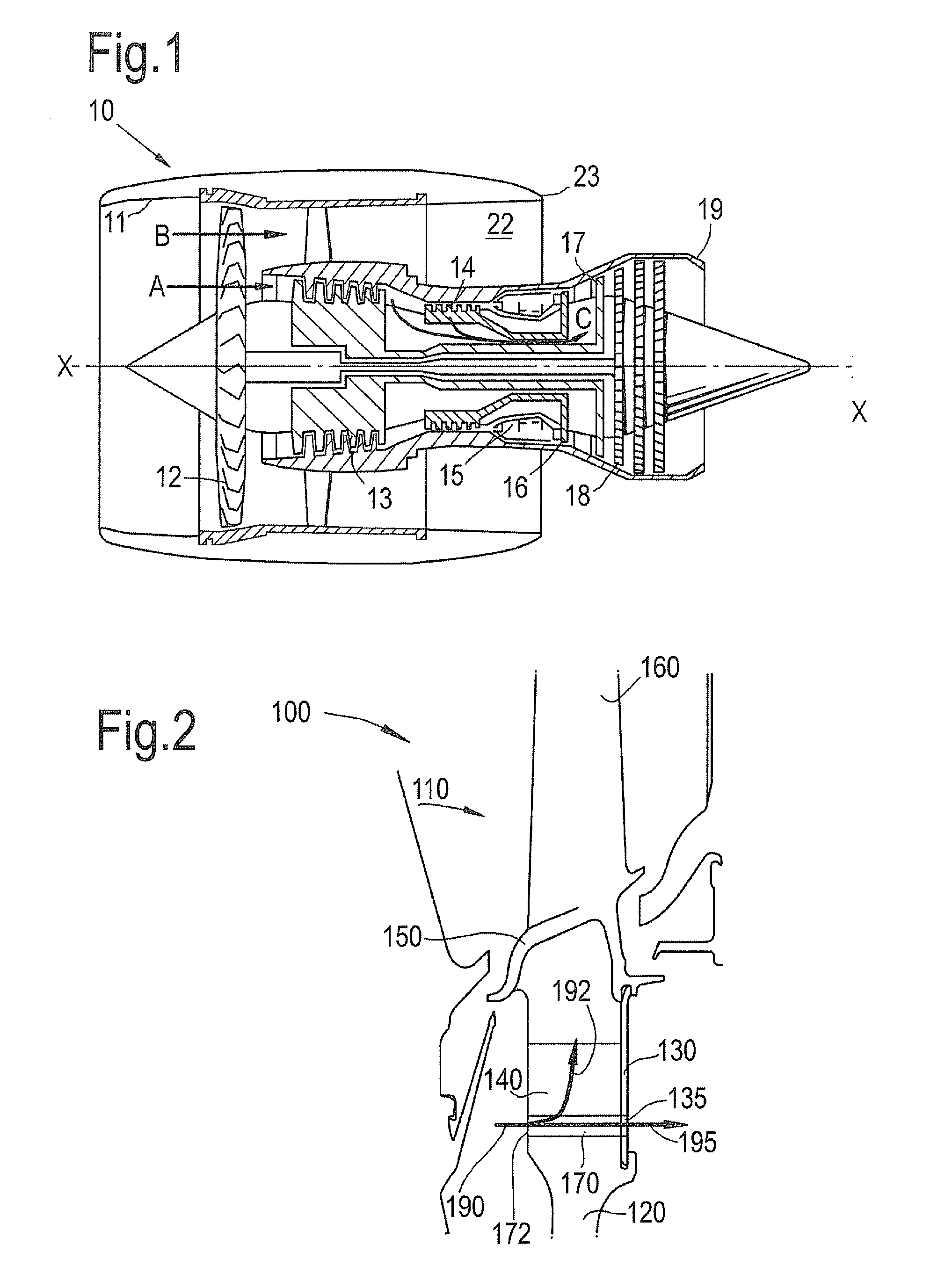
[0041]With reference to FIG. 1, a ducted fan gas turbine engine generally indicated at 10 has a principal and rotational axis X-X. The direction X-X may be referred to as the axial direction of the engine. The engine 10 comprises, in axial flow series, an air intake 11, a propulsive fan 12, an intermediate pressure compressor 13, a high-pressure compressor 14, combustion equipment 15, a high-pressure turbine 16, an intermediate pressure turbine 17, a low-pressure turbine 18 and a core engine exhaust nozzle 19. A nacelle 21 generally surrounds the engine 10 and defines the intake 12, a bypass duct 22 and a bypass exhaust nozzle 23.

[0042]The gas turbine engine 10 works in a conventional manner so that air entering the intake 11 is accelerated by the fan 12 to produce two air flows: a first air flow A into the intermediate pressure compressor 13 and a second air flow B which passes through the bypass duct 22 to provide propulsive thrust. The intermediate pressure compressor 13 compress...


PUM


Abstract

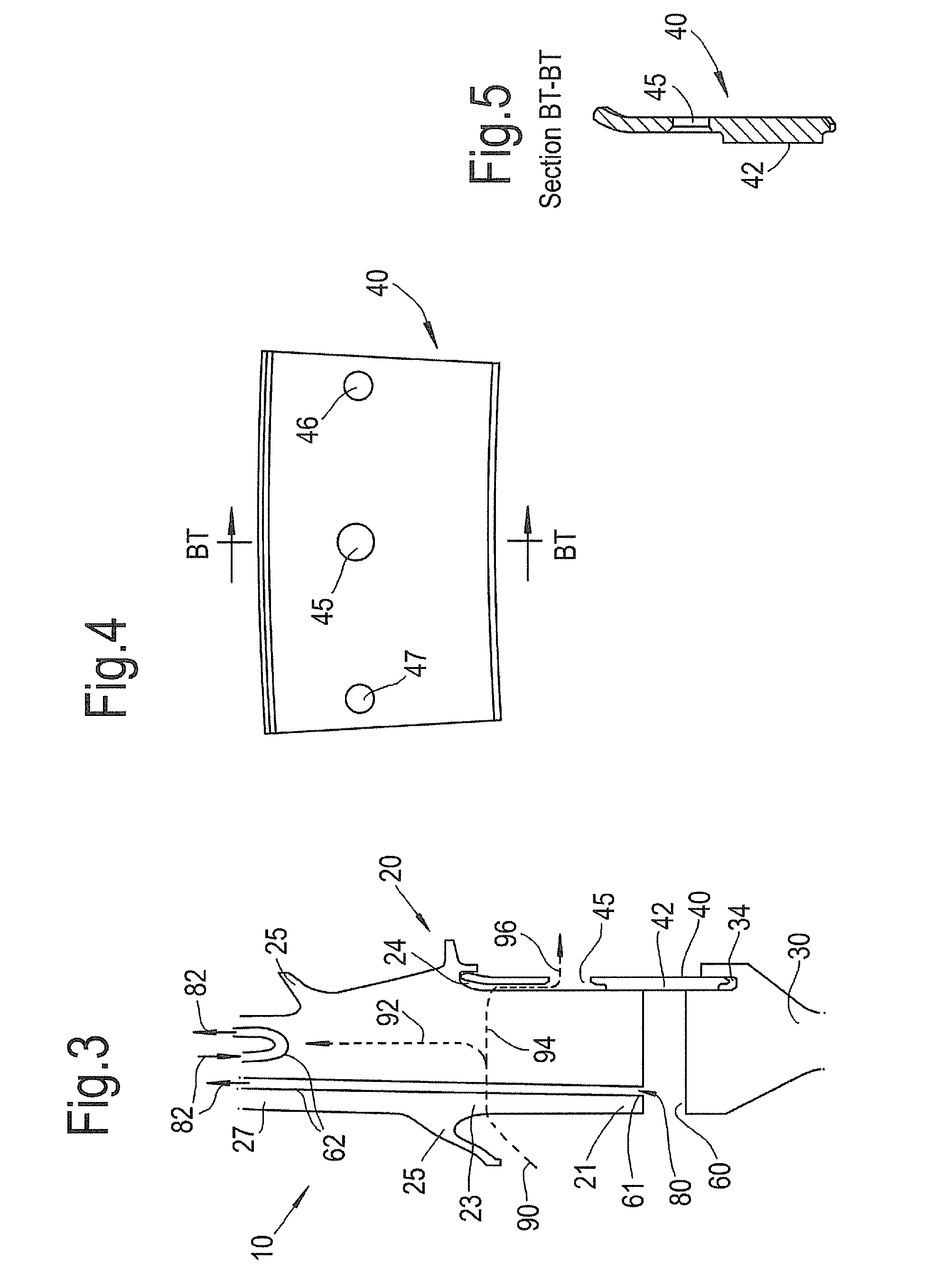
A rotor stage is provided which comprises a shank passage for separating liquid from secondary air system (SAS) air. The shank passage is formed between a radially outer surface of a disc post, a radially inner surface of one or more blade platforms, and the shanks of two neighbouring blades. In use,SAS air is supplied to the shank passage. Any liquid, such as oil, is separated from the SAS air due to the centripetal acceleration of the rotation of the rotor disc. The separated oil can then flow, or seep, past the blade platform and into the working fluid. The remainder of the SAS air passes through a hole in a sealing plate at the downstream end of the rotor stage, thereby providing SAS air with a lower liquid content for use downstream of the rotor stage.

Description

CROSS-REFERENCE TO RELATED APPLICATIONS[0001]This application is based upon and claims the benefit of priority from British Patent Application Number 1113893.0 filed 12 Aug. 2011, the entire contents of which are incorporated by reference.BACKGROUND OF THE INVENTION[0002]1. Field of the Invention[0003]The present invention relates to separation of oil from flow through a gas turbine engine. In particular, the present invention is at least in part concerned with separation of oil mist from secondary flows through a gas turbine engine, for example from internal flow through a rotor stage.[0004]2. Description of the Related Art[0005]A gas turbine engine typically has a working fluid, or working gas, that passes through the engine to generate power. The working fluid may refer to the core flow from which the turbine extracts work, after the core flow has been compressed in the compressor and combusted in the combustor.[0006]In addition to the working fluid, or core flow, a gas turbine e...

Claims


Application Information

Patent Timeline
Patent Type & Authority Applications(United States)
IPC IPC(8): F01D25/18F01D5/18F01D5/30
CPCF01D5/3015F01D11/001F01D5/081Y02T50/60
Inventor BURT, ALEXANDER J.SADLER, KEITH C.
Owner ROLLS ROYCE PLC
Learn More