Mobile light tower

a technology of mobile light tower and extendable mast, which is applied in the field of mobile light tower, can solve the problems of lowering the extendable mast, and achieve the effects of less leverage, safe operation in higher wind speeds, and lower the extendable mas

Inactive Publication Date: 2013-02-14
TIMMINS DAVID G +1
View PDF7 Cites 24 Cited by
  • Summary
  • Abstract
  • Description
  • Claims
  • Application Information

AI Technical Summary

Benefits of technology

[0010]The controller may be adapted to lower the extendable mast to an intermediate position, between the retracted position and the extended position, when a predetermined wind speed, e.g., a first predetermined wind speed, is detected by the wind speed sensor. The controller may be adapted to further lower the extendable mast from the intermediate position when the wind speed sensor determines a second predetermined wind speed or an nth predetermined wind speed is exceeded. This is advantageous as it helps the mobile light tower operate safely and remain operational. In particular, when in the fully extended position, the lighting rig will typically experience the highest winds. A given wind force acting on a fully extended mast also applies the most leverage to the base unit. Thus, the controller can lower the light rig to a lower position where the wind may be slower and the lighting rig applies less leverage to the base unit. If the wind persists and the second or nth predetermined wind speed is exceeded, the extendable mast may be lowered further or to the fully retracted position.
[0011]The second predetermined wind speed may be the same as or different from (i.e. higher or lower than) the first predetermined wind speed. This is advantageous as the controller may determine that safe operating conditions are still not experienced at the lower position, and therefore lower the extendable mast further. Since the mobile lighting tower may be able to operate safely in higher wind speeds when in the lower position, the second predetermined wind speed may be higher than the first predetermined wind speed. This allows the mobile lighting tower to be operational and safe during windy conditions.
[0012]The height of the lower intermediate positio

Problems solved by technology

The mobile light tower can react to adverse weather conditions that could pose

Method used


Image

  • Mobile light tower
  • Mobile light tower
  • Mobile light tower

Examples


Embodiment Construction

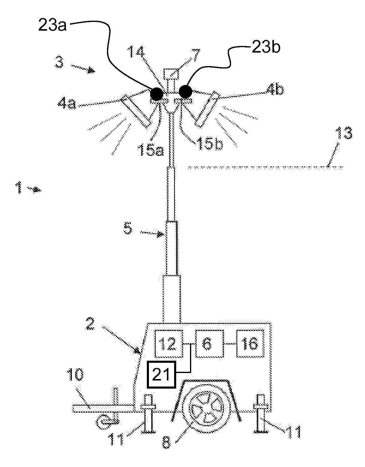
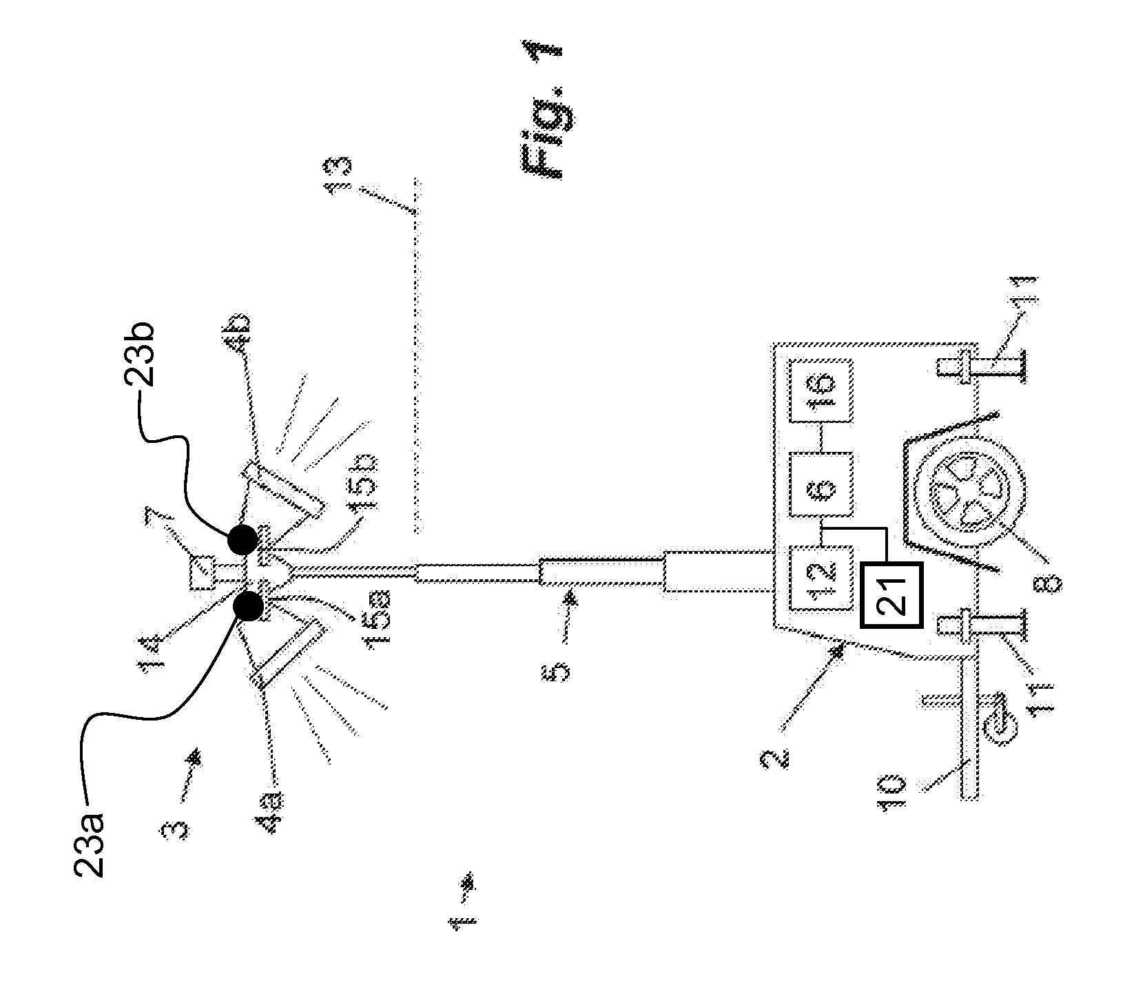
[0024]FIG. 1 shows an embodiment of a mobile light tower 1 for use on building sites, roadworks, or car parks, for examples. The mobile light tower is set up to provide illumination of an area so that a workforce can operate at night or car park users can find their cars more easily. It will be appreciated that these are only examples and the mobile light tower has many other uses.

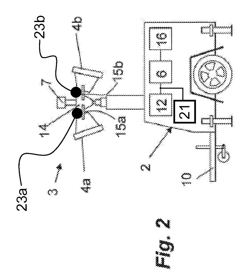
[0025]The mobile light tower 1 may comprise a base unit 2 and a light rig 3 including at least one light, for example, lights 4a and 4b. In some embodiments, more or fewer than two lights may be provided. The light rig 3 is connected to the base unit 2 by an extendable mast 5. The base unit 2 includes a power source 21 comprising, for example, a diesel powered generator for generating electricity for powering the lights 4a, 4b. The extendable mast 5 is adapted to move between a retracted position (shown in FIG. 2) and an extended position (shown in FIG. 1). The mobile light tower 1 includes a controller 6 ...


PUM


Abstract

A mobile light tower (1) comprising a base unit (2) and at least one light (4a, 4b) connected to the base unit by an extendable mast (5), the base unit including a power source for powering the at least one light, the extendable mast (5) adapted to move between a retracted position and an extended position, wherein the mobile light tower includes a controller (6) and a wind speed sensor (7), the controller adapted to lower the extendable mast to an intermediate position, between the retracted position and extended position, when the wind speed sensor (7) determines that a predetermined wind speed is exceeded.

Description

CROSS-REFERENCE[0001]This application is based on and claims priority from GB 1113704.9, filed on Aug. 9, 2011, with the UK Intellectual Property Office. The aforementioned patent application contains subject matter related, in certain aspects, to the subject matter of the present invention. The disclosure of this patent application is therefore incorporated by reference in the specification of the present invention.FIELD OF THE INVENTION[0002]This invention relates to a mobile light tower. It also relates to a controller for a mobile light tower.BACKGROUND OF THE INVENTION[0003]Mobile light towers comprise a base, an extendable mast and a light rig to which lighting units are mounted. The base typically comprises a power source mounted on a wheeled trailer, which can be towed by a vehicle. The light rig is connected to the base by the extendable mast, which can raise the light rig to a predetermined height above the base.[0004]A problem with mobile light towers is that they can be ...

Claims


Application Information

Patent Timeline
IPC IPC(8): F21L4/02F21V21/00
CPCF21L14/04F21S9/04F21V23/0492F21V21/22F21V21/15B60P3/18F21V21/36F21W2131/1005
Inventor JONES, PAUL MICHAELTIMMINS, DAVID GARY
Owner TIMMINS DAVID G
Why Eureka
Try Eureka