
Method and apparatus for detecting tightness of threaded joints of drill rods

Inactive Publication Date: 2013-02-14
SANDVIK MINING & CONSTR OY
View PDF3 Cites 5 Cited by
  • Summary
  • Abstract
  • Description
  • Claims
  • Application Information

AI Technical Summary

Benefits of technology

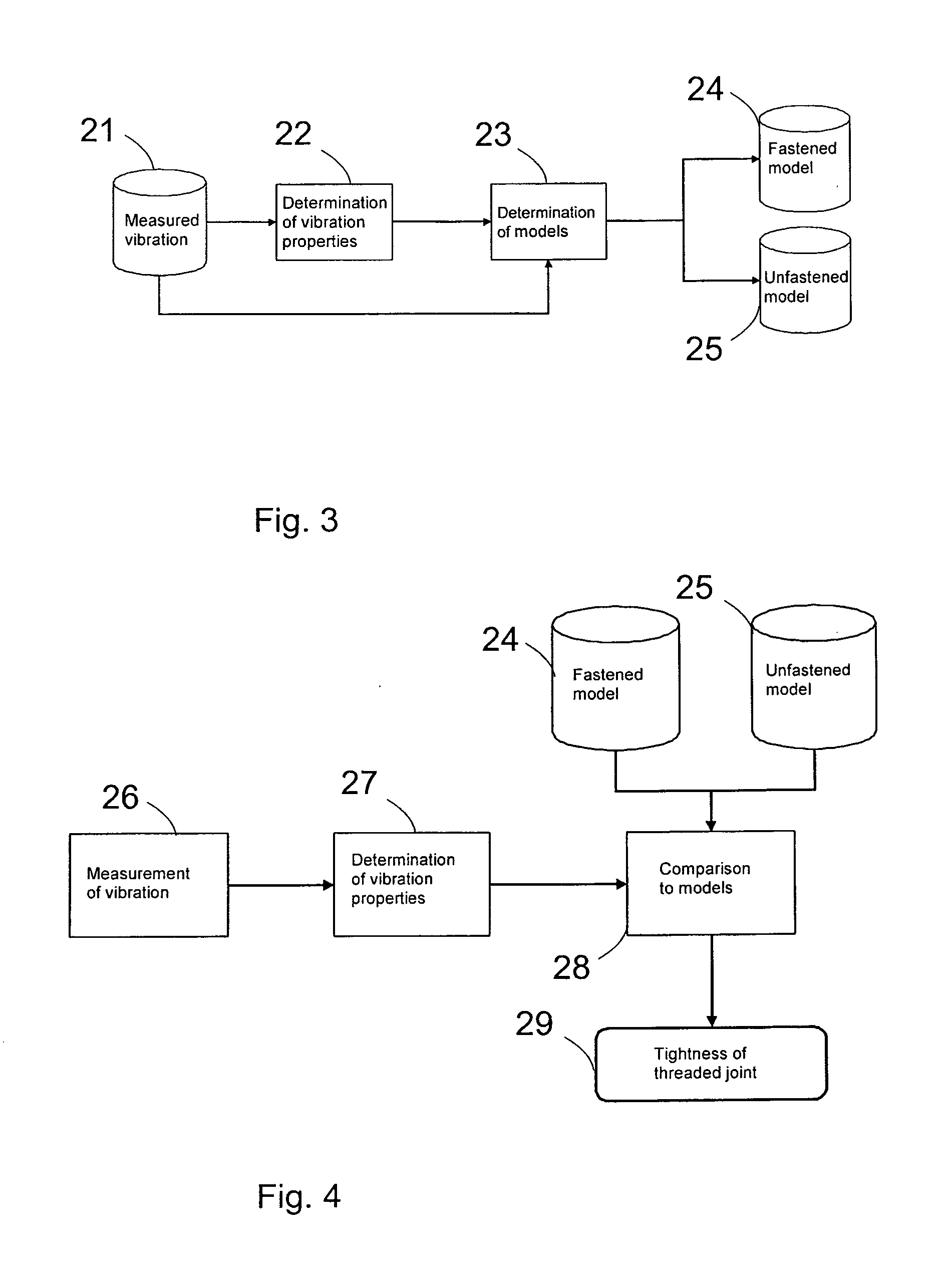
The invention provides a method and apparatus for reliably and automatically loosing threads in a threaded joint. The method involves measuring vibrations during impacting and comparing them with models of fastened and unfastened joints. By comparing the models, the method can determine the tightness of the joints without the need for accurate congruence of models. This makes the method easier to automate and requires no change in the position of the threshold condition. The apparatus includes a device that can measure vibrations during impacting and compare them with pre-defined models, allowing for reliable and automatic loosening of threads.

Problems solved by technology

During drilling, the threaded joints tighten up due to both rotation torque and impacts delivered thereto during drilling by a percussion device and the resulting waves of stress and torsion, and, in practice, they are generally unopenable by a rotating motor alone.
As known, attempts have been made to solve this problem such that after completed hole drilling the operator has impacted the drill rods with the percussion device, when feed force is not exerted thereon, whereby a suitable number of impacts causes the threads to loosen.
In practice, the problem is that it is difficult to detect the loosening of the threads in a reliable manner and it does not always succeed the first time.
Another problem is that unnecessary impacting, when the threads are already unfastened, may wear and even damage the drilling equipment.
In addition, there is a risk that the threaded joints come open completely and parts of the drilling equipment are detached from one another and fall in the hole.
Further, the fact that the operator has to perform this manually prevents automation.
However, solutions disclosed in these publications are not, in practice, fully reliable in operation.
These require either highly detailed and precise, characteristic vibration patterns or case-specific values, and nevertheless their use is limited almost device-specifically such that settings for one device cannot be used in other similar devices or as conditions change.

Method used


Image

  • Method and apparatus for detecting tightness of threaded joints of drill rods
  • Method and apparatus for detecting tightness of threaded joints of drill rods
  • Method and apparatus for detecting tightness of threaded joints of drill rods

Examples


Embodiment Construction

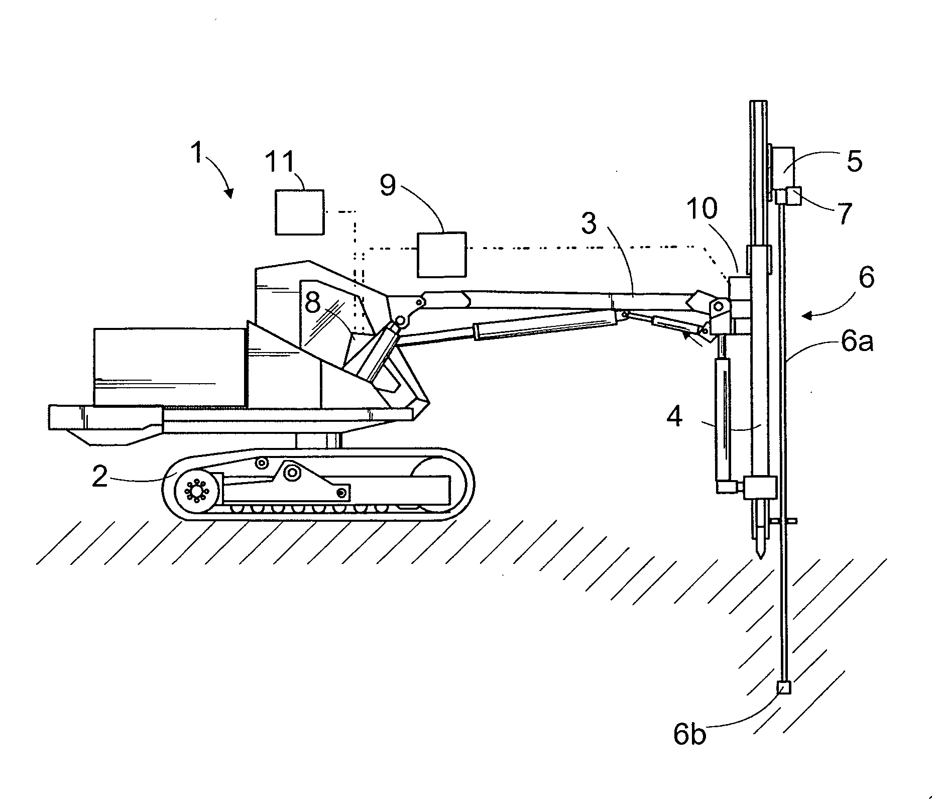
[0020]FIG. 1 shows schematically a rock drilling rig 1 comprising a carrier 2, to which a boom 3 is connected. At one end of the boom 3 there is connected a feed beam 4 along which a rock drilling machine 5 moves during use. To the rock drill 5 is coupled drilling equipment 6 which is rotated and impacted with a percussion device, included in the rock drill, during drilling.

[0021]The drilling equipment 6 comprises one or more drill rods 6a and a drill bit 6b, which are interconnected by threaded joints in a manner known per se. In other rock drilling rigs, the drilling equipment also includes a drill shank, which is not shown here but which is known per se to a person skilled in the art and which is generally located inside the rock drilling machine. Rock drilling rigs of this kind, and the operation thereof, are commonly known per se, and therefore they need not be described in detail.

[0022]The rock drilling machine 5 of the rock drilling rig 1 comprises a percussion device known p...


PUM


Abstract

The invention relates to a method and an apparatus for detecting tightness of threaded joints of drill rods when unfastening at least one threaded joint of the drilling equipment (6) by impacting the drilling equipment (6) with a percussion device in the rock drilling rig (1). For detecting the tightness there is predetermined at least one fastened model for a situation where the threaded joint / joints are fastened, a vibration signal measured during impacting is compared with both the fastened model and the unfastened model and, on the basis of the comparison, it is determined to which one of the models the tightness of the threaded joints better corresponds at the moment of determination.

Description

BACKGROUND OF THE INVENTION[0001]The invention relates to a method for detecting tightness of threaded joints of drill rods when unfastening at least one threaded joint of drilling equipment by impacting the drilling equipment with a percussion device of a rock drilling rig, the method predetermining at least one unfastened model for a situation where the threaded joint is unfastened, based on vibration produced in the drilling equipment while being impacted, measuring vibration originating from the drilling equipment during impacting and comparing a measured vibration signal with the model so as to determine the tightness in the threaded joint(s).[0002]Further, the invention relates to an apparatus for detecting tightness of threaded joints of drill rods when unfastening at least one threaded joint of drilling equipment by impacting the drilling equipment with a percussion device of a rock drilling rig, the apparatus comprising a control device for controlling the rock drilling rig...

Claims


Application Information

Patent Timeline
IPC IPC(8): F16B31/00E21B47/00
CPCE21B19/165E21B44/00E21B1/00
Inventor PIRINEN, TUOMOUITTO, VESAHAKALA, JOONAKLAPURI, ANSSI
Owner SANDVIK MINING & CONSTR OY
Learn More