
Working machine

Active Publication Date: 2013-02-14
KUBOTA LTD
View PDF6 Cites 27 Cited by
  • Summary
  • Abstract
  • Description
  • Claims
  • Application Information

AI Technical Summary

Benefits of technology

The present invention provides a system for controlling the pressure of a vehicle's engine to prevent stalling and increase the speed of travel. The system includes a pressure control valve and control unit that allow for independent adjustment of the engine's pressure under unloaded and loaded conditions, providing better performance and preventing engine stalling. Additionally, the system allows for effective recovery of the engine's speed after a sudden drop in speed. Overall, the invention improves performance and reliability of vehicles equipped with the system.

Problems solved by technology

Due to the provision of the bleed circuit, when the engine speed is dropped, the number of rotations of the pilot pump is decreased to decrease a discharge amount of the pilot pump, and a ratio of an oil leak from the bleed circuit with respect to the discharge amount of the pilot pump becomes large.

Method used


Image

  • Working machine
  • Working machine
  • Working machine

Examples


Embodiment Construction

[0060]Referring to drawings, an embodiment of the present invention will be explained below.

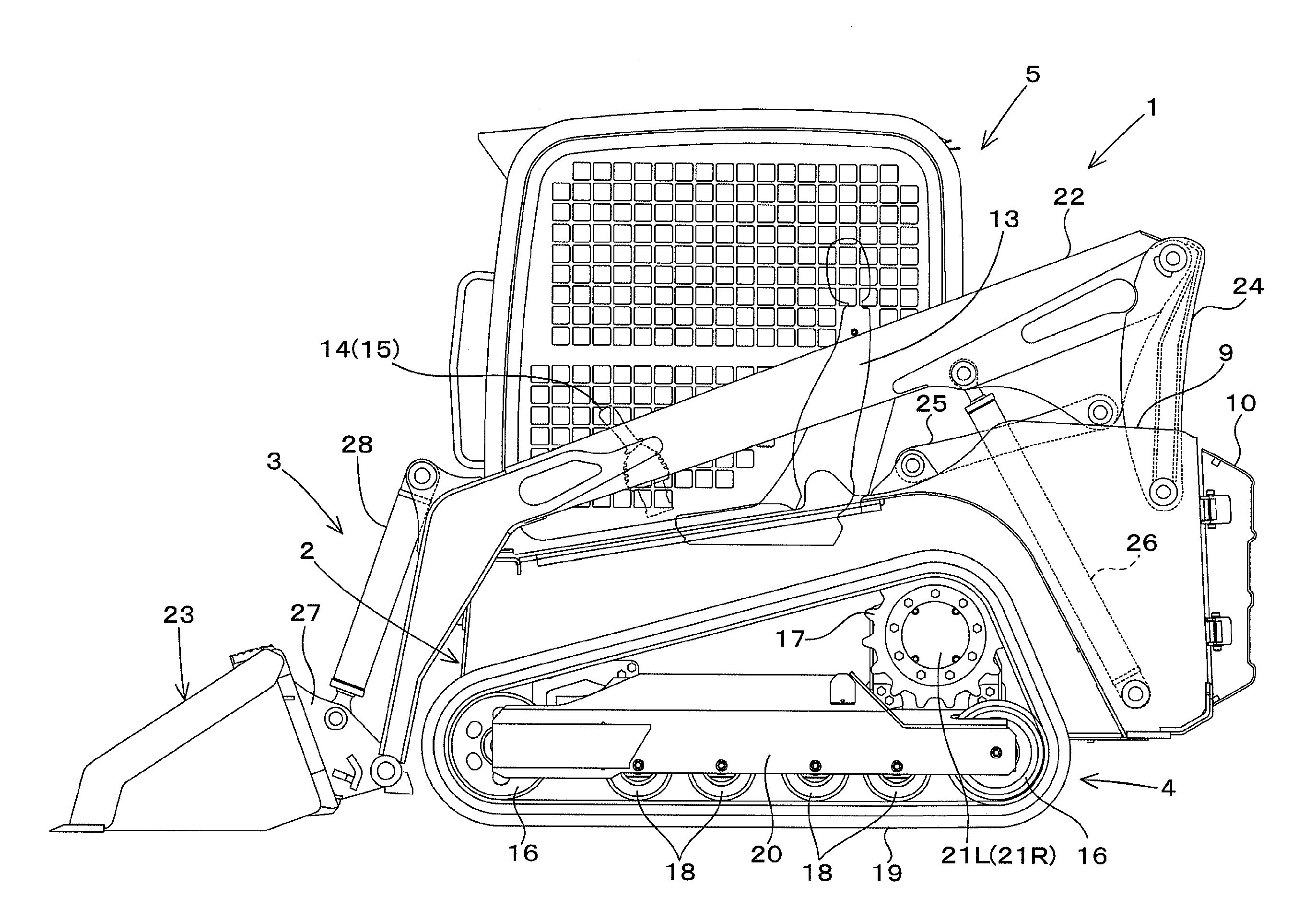
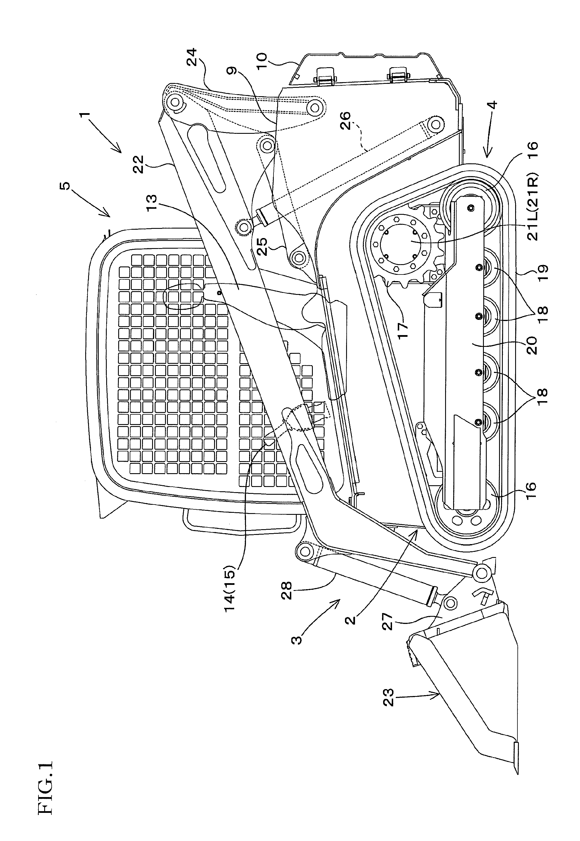
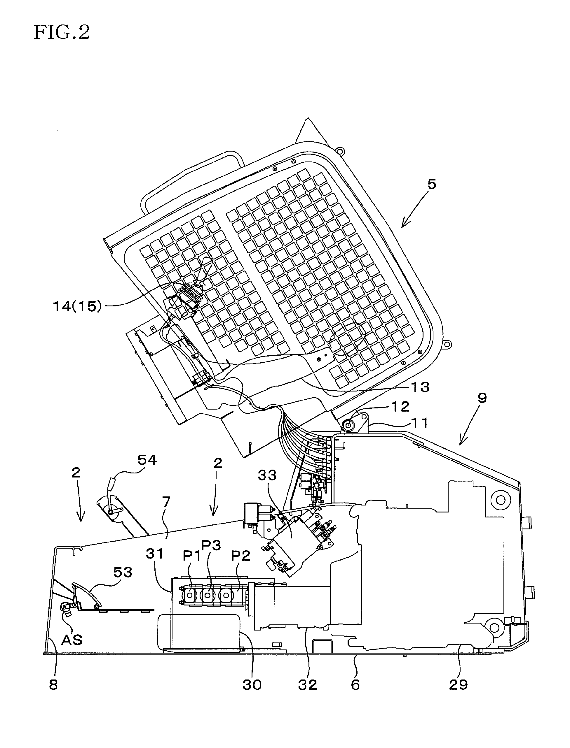
[0061]In FIG. 1 and FIG. 2, a reference numeral 1 is a track loader exemplified as a working machine according to the present invention, the track loader 1 includes: a machine body 2; a working device 3 attached to the machine body 2; and a right-and-left pair of traveling devices 4 for supporting the machine body 2 to be able to travel, and a cabin 5 (an operator protection device) is mounted near an upper front portion of the machine body 2.

[0062]The machine body 2 includes: a bottom wall 6; a right-and-left pair of side walls 7; a front wall 8; and a support frame body 9 provided to a rear portion of each of the right and left side walls 7, a space between the side walls 7 is opened upward, and a cover member 10 for covering a rear end opening between the right-and-left pair of support frame body 9 is provided to a rear end portion of the machine body 2 so as to be freely opened and closed...


PUM


Abstract

A pressure control valve for controlling a travel primary side pressure that is a pressure of a primary side of a travel operation device is controlled by a control unit, thus the travel primary side pressure is controlled, and thereby a traveling speed is intended to be increased, preventing an engine stall.

Description

TECHNICAL FIELD[0001]The present invention relates to a self-propelled working machine such as a Compact Track Loader (CTL), a Skid Loader, and a Backhoe.BACKGROUND ART[0002]There are track loaders described in Japanese Unexamined Patent Publications JP-A 2010-270527 and JP-A 2010-270528 as a self-propelled working machine.[0003]The track loader has a HST (Hydro Static Transmission) including: a HST pump composed of a tilted-plate type variable capacity pump driven by an engine; and a HST motor for driving a travelling device driven by a discharge oil from the HST pump, the HST motor being connected to the HST pump to be in a closed circuit with use of a pair of gear-changing oil passages.[0004]In addition, the track loader has a main pump and a pilot pump each driven by the engine, and has: a working device driven by a discharge oil of the main pump; and a travel operation device for controlling a tilted plate of the HST pump due to a discharge oil of the pilot pump.[0005]The worki...

Claims


Application Information

Patent Timeline
IPC IPC(8): F16D31/00
CPCF16H61/421B60Y2200/411F16H61/468
Inventor KINUGAWA, RYOSUKEMIURA, KEISUKETANAKA, ISAOARII, KAZUYOSHIFUKUDA, YUJI
Owner KUBOTA LTD
Learn More