
Hybrid Hotspot Detection

a hotspot detection and hybrid technology, applied in the field of hybrid hotspot detection, can solve the problems of serious resolution degradation, prolonged manufacturability closure, affecting product yield and reliability,

Active Publication Date: 2013-01-31
SIEMENS PROD LIFECYCLE MANAGEMENT SOFTWARE INC
View PDF0 Cites 33 Cited by
  • Summary
  • Abstract
  • Description
  • Claims
  • Application Information

AI Technical Summary

Benefits of technology

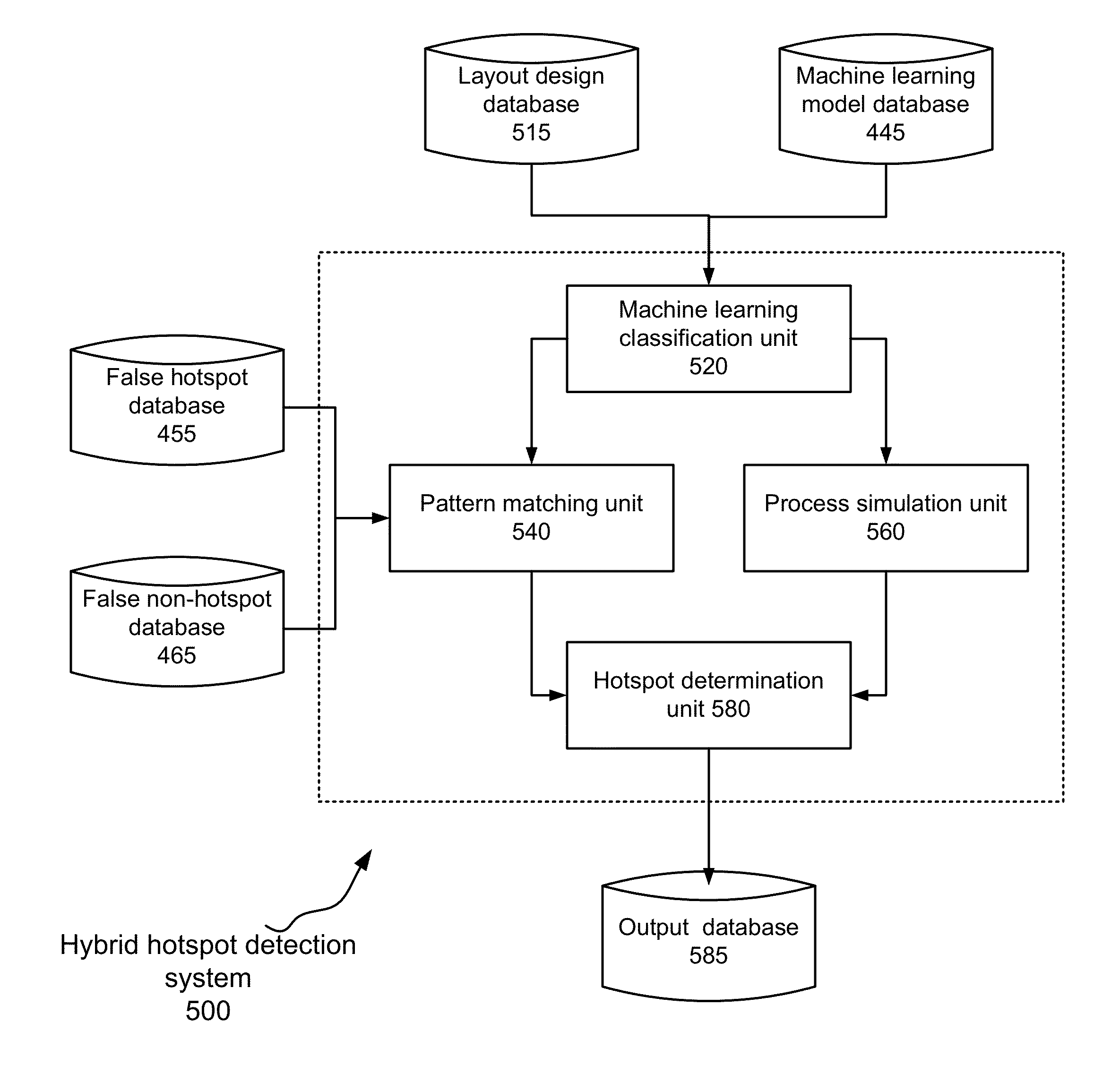
This patent relates to techniques for detecting hotspots in layout designs using a combination of machine learning, pattern matching, and process simulation. The invention combines a calibrated machine learning model with false hotspots and non-hotspots identified through pattern matching. The process simulation identifies boundary hotspats in the potential hotspots. The technical effect of the invention is improved accuracy in identifying hotspats in layout designs, which can aid in the manufacturing of complex integrated circuits.

Problems solved by technology

As the shrinking of device feature sizes brings advantages such as reduction of circuit switching power and manufacturing cost, it is also accompanied by the problem of prolonged manufacturability closure.
Printing sub-wavelength features results in serious resolution degradation, which affects a product's yield and reliability.
In their original form, geometrical rules are one-dimensional and their capability of describing two-dimensional patterns is limited.
As the rules are expanded to cover more complicated two-dimensional patterns, they either become overly conservative, or too relaxed to catch some hotspot patterns.
However, these techniques cannot completely resolve some printability problems.
However, this great accuracy comes at a price of high computational complexity and runtime.
A major drawback of these tools, however, is their inability to detect bad patterns that will cause printability problems but that are absent from the database of undesirable patterns.
However, such approaches are still largely ineffective in detecting previously unseen hotspot patterns.
However, challenges remain in improving their detection accuracy and efficiency.

Method used


Image

  • Hybrid Hotspot Detection
  • Hybrid Hotspot Detection
  • Hybrid Hotspot Detection

Examples


Embodiment Construction

[0014]Various aspects of the present invention relate to hotspot detection techniques. In the following description, numerous details are set forth for purpose of explanation. However, one of ordinary skill in the art will realize that the invention may be practiced without the use of these specific details. In other instances, well-known features have not been described in details to avoid obscuring the present invention.

[0015]Although the operations of some of the disclosed methods, apparatus, and systems are described in a particular, sequential order for convenient presentation, it should be understood that this manner of description encompasses rearrangement, unless a particular ordering is required by specific language set forth below. For example, operations described sequentially may in some cases be rearranged or performed concurrently. Moreover, for the sake of simplicity, the attached figures may not show the various ways in which the disclosed methods, apparatus, and sys...


PUM


Abstract

Aspects of the invention relate to hybrid hotspot detection techniques. The hybrid hotspot detection techniques combine machine learning classification, pattern matching and process simulation. A machine learning model, along with false hotspots and false non-hotspots for pattern matching, is determined based on training patterns. The determined machine learning model is then used to classify patterns in a layout design into three categories: preliminary hotspots, preliminary non-hotspots and potential hotspots. Pattern matching is then employed to identify false positives and false negatives in the first two categories. Process simulation is employed to identify boundary hotspots in the last category.

Description

FIELD OF THE INVENTION[0001]The present invention is directed to integrated circuit (IC) physical design verification. Various aspects of the invention may be particularly useful for detecting hotspots in a layout design.BACKGROUND OF THE INVENTIONOverview[0002]For the past few years, modern IC industry has been steadily following Moore's Law. As the shrinking of device feature sizes brings advantages such as reduction of circuit switching power and manufacturing cost, it is also accompanied by the problem of prolonged manufacturability closure. Printing sub-wavelength features results in serious resolution degradation, which affects a product's yield and reliability. Locations in a design where layout geometries will be printed with dimensions over or below specified threshold values are often referred to as lithographic hotspots or hotspots. Two common categories of the hotspots are pinching and bridging.[0003]Traditionally, appropriate rules are checked at various design stages (...

Claims


Application Information

Patent Timeline
Patent Type & Authority Applications(United States)
IPC IPC(8): G06F17/50
CPCG06F17/5081G06F30/398
Inventor ROBLES, JUAN ANDRES TORRESFAHMY, SALMA MOSTAFABESHAY, PETER LOUIZ REZKMADKOUR, KAREEMPIKUS, FEDOR G.WUU, JEN-YIDING, DUO
Owner SIEMENS PROD LIFECYCLE MANAGEMENT SOFTWARE INC
Learn More