
Radar system and method of manufacturing same

a technology of radar system and manufacturing method, applied in the field of microelectromechanical system (mems) radar system, can solve the problems of reducing the complexity of the system, reducing the latency and cycle time, and reducing the size of the device package, so as to achieve accurate and reliable radar signaling

Active Publication Date: 2013-01-31
UNIVERSITY OF WINDSOR
View PDF29 Cites 209 Cited by
  • Summary
  • Abstract
  • Description
  • Claims
  • Application Information

AI Technical Summary

Benefits of technology

The invention is an improved radar system using MEMS technology to provide accurate and reliable radar signaling in a small device package at high speeds. The radar system incorporates a Rotman lens which generates a plurality of time delayed, in phase signals necessary for beamforming, by exploiting the physical geometry of the lens cavity, reducing processing requirements for electrical switches or microelectronics-based switching for phase-shifters. The use of RF switches and a Rotman lens reduces the amount of signal processing, resulting in lower system complexity, lower latency time and faster cycle time. The radar system also utilizes a Transverse Electric (TE) mode, air-filled Rotman lens which is constructed using MEMS technology and exhibits lower 1 / f noises, a small foot print area, lower interference from other users and Pulse radar signals, a high reflection intensity, and a large radar cross section (RCS). The entire radar system can be incorporated into a small device package.

Problems solved by technology

The combination of RF switches and a Rotman lens reduces the amount of signal processing, resulting in lower system complexity, lower latency time and faster cycle time.
Furthermore, a radar system incorporating a Rotman lens constructed using MEMS technology results in a much smaller device package.

Method used


Image

  • Radar system and method of manufacturing same
  • Radar system and method of manufacturing same
  • Radar system and method of manufacturing same

Examples


Embodiment Construction

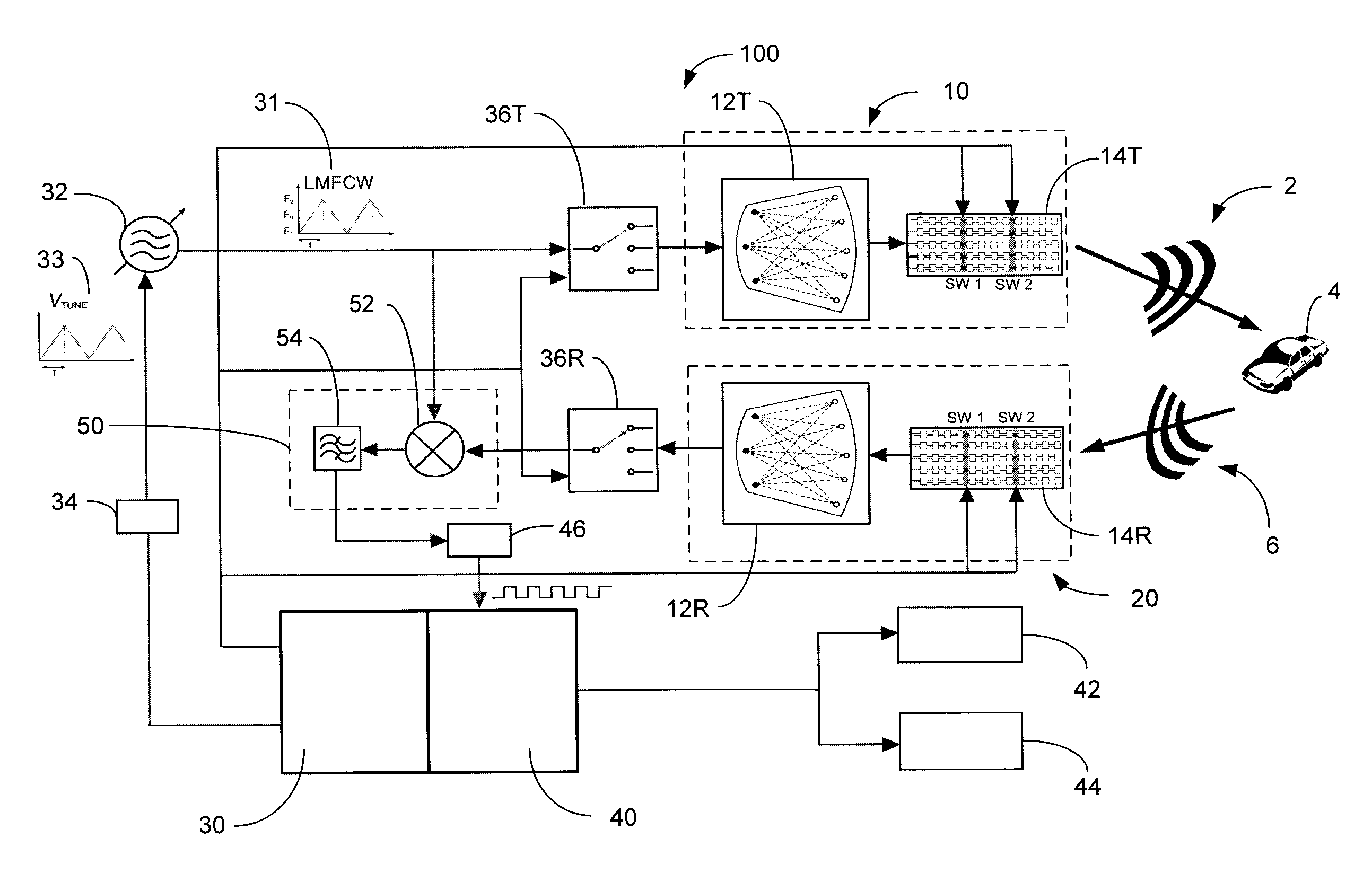
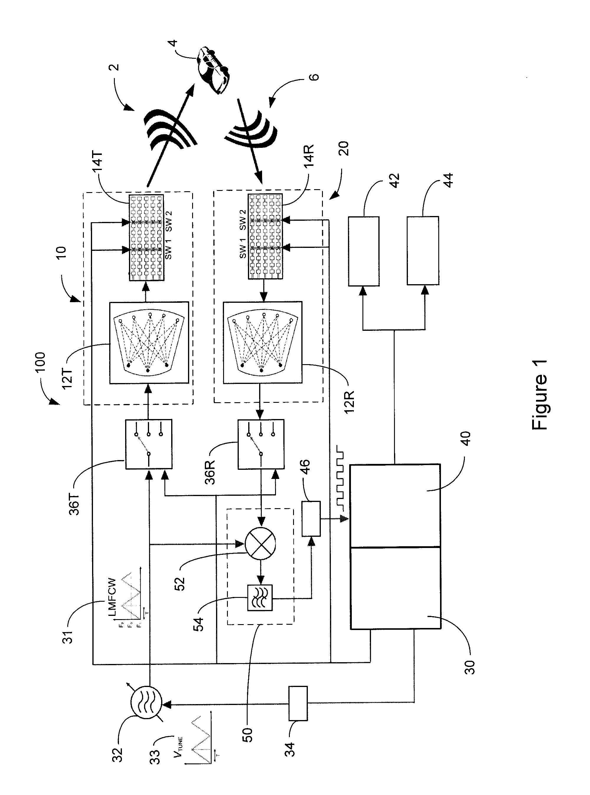
[0046]Reference is made to FIG. 1, which shows schematically a radar system 100 in accordance with an embodiment of the present invention. The radar system 100 has an overall size selected to enable its mounting on or in the bumper of a host vehicle 8 (FIG. 12). The radar system 100 includes a transmitting assembly 10, a receiving assembly 20, a control unit 30, and a signal processing unit 40. As will be described, the transmitting assembly 10 is operable to transmit an incident radar signal 2 at the target vehicle 4. The receiving assembly 20 is operable to receive the reflected radar signal 6 from the target vehicle 4, and which is then processed by the signal processing unit 40 to extract information relating to the location, speed and / or direction of the target vehicle 4 and then provided to the user as an output 5. The reflected radar signal 6 optionally may be subjected to analog filtering prior to being passed to the signal processing unit 40. For example, an analog filter a...


PUM


Abstract

A radar system (100) is described including a transmitting assembly (10), a receiving assembly (20), a control unit (30) and a signal processing unit (40). The transmitting assembly (10) receives an input signal (31) and transmits an incident radar signal (2). The transmitting assembly (10) includes a Rotman lens (12) having a lens cavity (74), a plurality of beam ports (60), a plurality of array ports (62) and a patch antenna assembly (14). The lens cavity (74) has a lens gap (h) between 10 microns to 120 microns, and preferably 40 microns to 60 microns. The patch antenna assembly (14) includes a plurality of antenna arrays (130) operable to receive a plurality of time-delayed, in-phase signals from the Rotman lens (12) and to transmit the incident radar signal (2) towards a target (4). The receiving assembly (20) receives a reflected radar signal (6) and produces an output signal. The signal processing unit (40) compares the input signal (31) to the output signal and implements an algorithm determining the range, velocity and position of the target (4).

Description

RELATED APPLICATIONS[0001]This application claims the benefit of 35 USC 119(e) to U.S. Provisional Patent Application Ser. No. 61 / 282,595, filed 5 Mar. 2010.FIELD OF THE INVENTION[0002]This invention relates to micro-electromechanical systems (MEMS) radar systems for measuring the location, velocity and range of a target and methods of manufacturing. More particularly as will be described in a preferred embodiment, this invention relates to a radar system which includes: passive beamforming, circuit integration of electrical to electromagnetic to electrical to electromagnetic signal processing in the transmission and reception of a radar signal and multimodal capability.BACKGROUND OF THE INVENTION[0003]Radar systems are well known in the art to detect objects and targets using electromagnetic waves. Traditionally, radio waves or pulses have been transmitted by a radar dish or antenna to bounce off an object in their path. The reflected wave is then returned to a receiver and compare...

Claims


Application Information

Patent Timeline
Patent Type & Authority Applications(United States)
IPC IPC(8): G01S7/03G01S13/931
CPCG01S7/032H01Q25/008G01S13/422G01S13/584G01S13/931G01S2013/0245H01Q1/34H01Q9/0407H01Q21/0031H01Q21/0087H01Q21/065G01S2013/9389G01S2013/9314G01S2013/9375G01S2013/9378G01S2013/9385G01S13/345G01S2013/93275G01S2013/93274G01S2013/93272G01S2013/93271H01Q13/206
Inventor CHOWDHURY, SAZZADUR
Owner UNIVERSITY OF WINDSOR
Learn More