
Boat with a latch assembly

a technology of latch assembly and boat, which is applied in the field of boats, can solve the problems of two-legged latch mechanism drawbacks, noise, and easy damage of latches, and achieve the effects of low force, easy use, and little to no damag

Inactive Publication Date: 2013-01-31
AVALON PONTOONS
View PDF3 Cites 7 Cited by
  • Summary
  • Abstract
  • Description
  • Claims
  • Application Information

AI Technical Summary

Benefits of technology

The invention provides a latch assembly for a boat with a sliding member and a glide plate made of low-friction material, which allows for smooth sliding between the latched and unlatched positions. The latch assembly is easier to use and allows for the use of hard, durable materials for the base and sliding members, giving the boat a more luxurious appearance. Additionally, the invention includes a strike arm on the gate and a strike surface on the base member, which protects the wall segment from damage if someone slams the gate.

Problems solved by technology

While effective at latching the gate in the closed position and being simply constructed, such two-legged latch mechanisms have their drawbacks.
Such latches are prone to damage since excessive opening or closing pressure applied to the gate is born by one or the other legs, and they can bend under excessive load.
The spacing of the legs on either side of the gate when in the closed position and the metal-to-metal contact if the latch is made of aluminum makes such latches prone to noise, as the gate may have a tendency to rattle back and forth against the legs during operation of the boat.
Making such two-legged latches out of plastics material is an option to alleviate the noise issues and reduce the opportunity for bending, but such plastics materials also have their limits and are prone to breakage and possible deterioration with prolonged exposure to the elements.
In addition to their functional limitations, such two-legged latches are very utilitarian and may lack the appearance desired for higher end boat applications.

Method used


Image

  • Boat with a latch assembly
  • Boat with a latch assembly
  • Boat with a latch assembly

Examples


Embodiment Construction

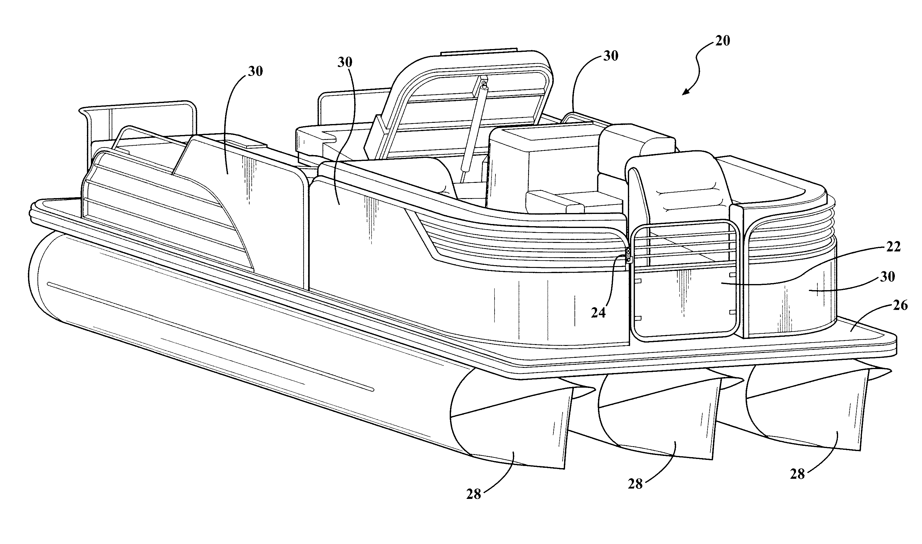
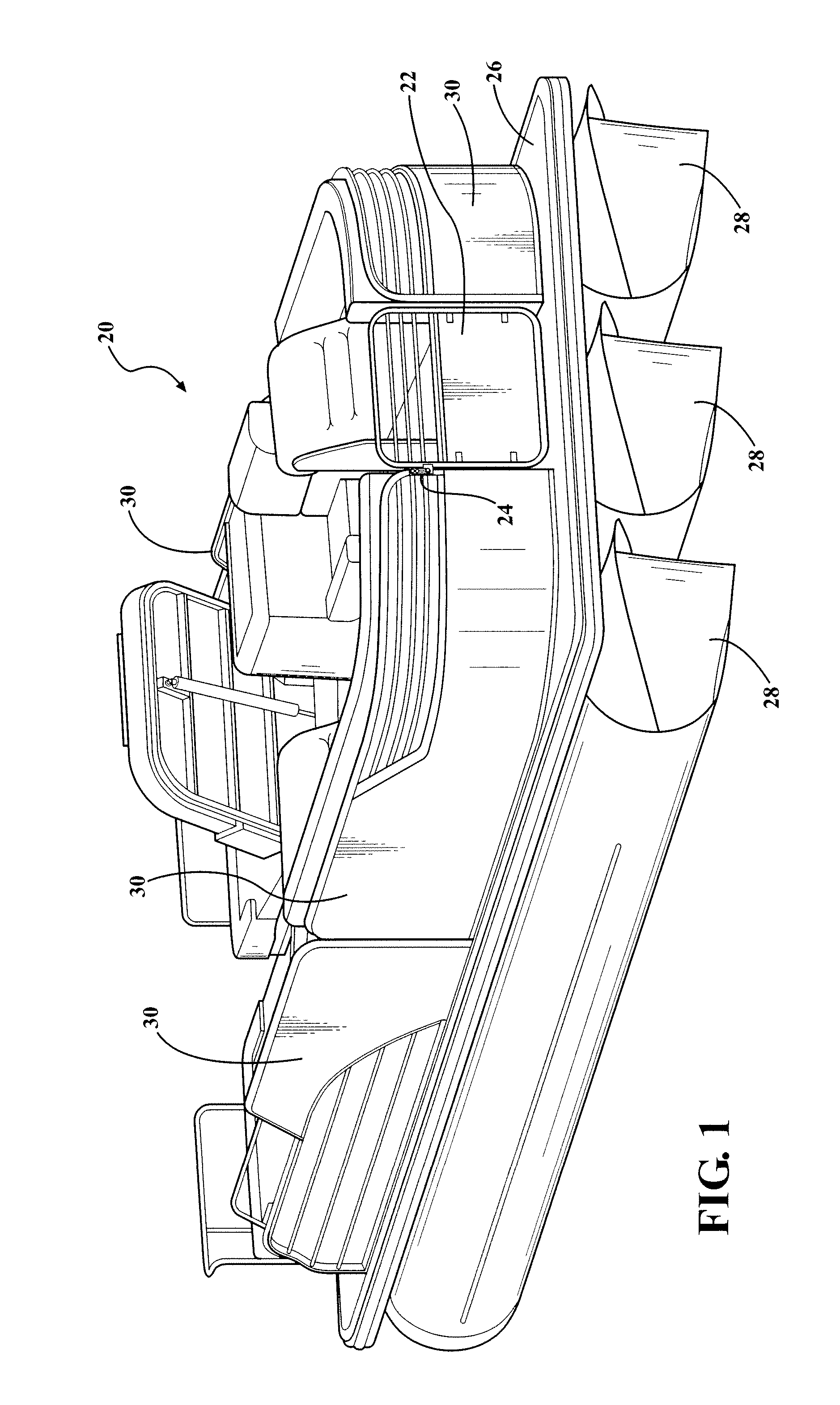
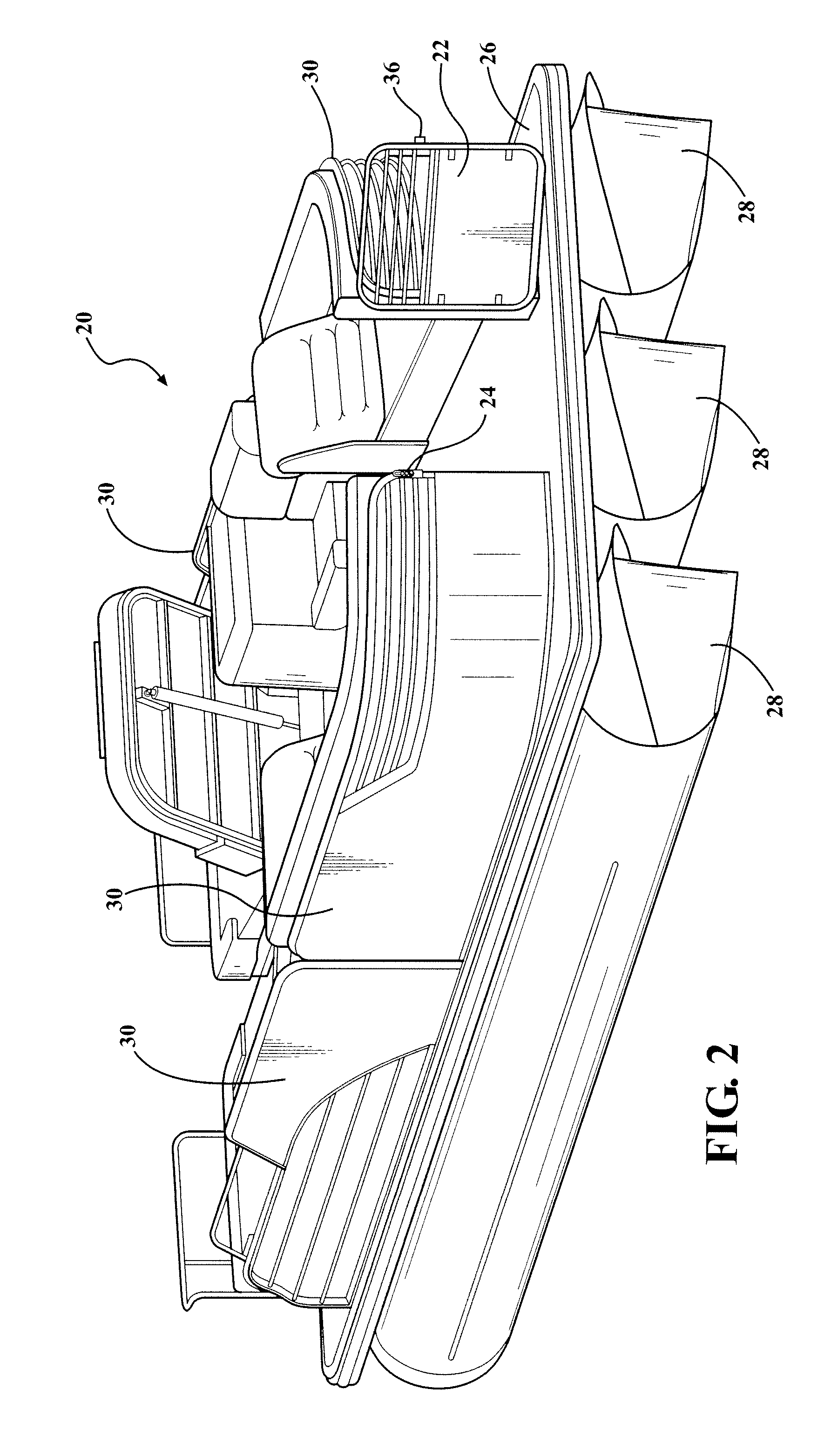
[0025]Referring to the Figures, wherein like numerals indicate corresponding parts throughout the several views, an exemplary pontoon boat 20 with a gate 22 and a latch assembly 24 is generally shown in FIGS. 1 and 2. It should be appreciated that the boat does not have to be a pontoon boat 20 as shown in the exemplary embodiment, but instead could be any other type of boat including, for example, a ski boat, a yacht or a sail boat. The exemplary pontoon boat 20 includes a deck 26 supported by three pontoons 28 extending in spaced and parallel relationship with one another. When placed in a body of water, the pontoons 28 floatably support the deck 26 and the rest of the pontoon boat 20. It should be appreciated that the pontoon boat 20 could include any desirable number of pontoons 28 to floatably support the deck 26.

[0026]The pontoon boat 20 includes a plurality of wall segments 30 disposed on the deck 26 and extending generally upwardly therefrom to define an interior space of the...


PUM

PropertyMeasurementUnit
frictionaaaaaaaaaa
heightaaaaaaaaaa
diameteraaaaaaaaaa

Abstract

A boat including at least two wall segments extending generally upwardly from a deck to define an interior space. The wall segments are spaced from one another to define a passage for allowing passengers to enter and exit the interior space. A gate is secured to one of the wall segments for controlling access to the interior space. A latch assembly including base and sliding members is coupled to an end of one of the wall segments. The sliding member is movable between a latched position for trapping a portion of the gate and an unlatched position for releasing the gate. At least one glide plate of a low-friction material is disposed between the base and sliding members. Additionally, when the sliding member is in the unlatched position, the base member presents a strike surface for receiving contact from the gate to protect the wall segment.

Description

BACKGROUND OF THE INVENTION[0001]1. Field of the Invention[0002]The subject invention is related to a boats. More specifically, the subject invention is related to boats having a gate and a latch assembly.[0003]2. Description of the Related Art[0004]Recreational boats are continuously improving and becoming increasingly luxurious. Many boats, such as pontoon boats, include a gate extending between two wall segments and rotatable between open and closed positions for controlling access into and out of the interior space of the boat. The gate is releasably secured in the closed position with a latch assembly.[0005]One type of latch assembly employed in many pontoon boats includes a pivoting member which is rotatably secured to one of the wall segments and presents a pair of outwardly extending legs which are spaced from one another by a width that is slightly greater than the width of the gate. When the gate is moved to the closed position, a user can rotate the two-legged latch downw...

Claims


Application Information

Patent Timeline
Patent Type & Authority Applications(United States)
IPC IPC(8): B63B17/00B23P11/00
CPCE05B65/0007E05B15/0093E05B17/007Y10T29/49826E05C1/04B63B2017/045B63B19/00
Inventor COONEY, JOHN R.
Owner AVALON PONTOONS
Learn More