Ventilation control system and method

a ventilation control and ventilation system technology, applied in ventilation systems, heating types, instruments, etc., can solve problems such as health risks, damage or destruction of structures, food items, equipment, etc., and achieve the effect of preventing the damage of the structure or obj

Active Publication Date: 2013-01-24
GTR TECH
View PDF11 Cites 18 Cited by
  • Summary
  • Abstract
  • Description
  • Claims
  • Application Information

AI Technical Summary

Problems solved by technology

Moisture vapor, which is the presence of condensed water in the surrounding air, can pose a health risk, and condensate resulting from water in the air can damage or destroy structures, equipment, pharmaceuticals, and food items.
Such organisms threaten the health of occupants and the integrity of the structures or objects stored therein.

Method used


Image

  • Ventilation control system and method
  • Ventilation control system and method
  • Ventilation control system and method

Examples


Embodiment Construction

[0025]Further aspects of the system and method will become apparent from consideration of the drawings and the ensuing description of preferred embodiments of the disclosure. A person skilled in the art will realize that other embodiments of the disclosure are possible and that the details of the apparatus can be modified in a number of respects, all without departing from the scope of the disclosure. Thus, the following drawings and description are to be regarded as illustrative in nature and not restrictive.

[0026]In the following description, certain specific details are set forth in order to provide a thorough understanding of various embodiments of the disclosure. However, one skilled in the art will understand that the disclosure may be practiced without these specific details. In other instances, well-known structures associated with switches, sensors, and controllers have not been described in detail to avoid unnecessarily obscuring the descriptions of the embodiments of the ...


PUM


Abstract

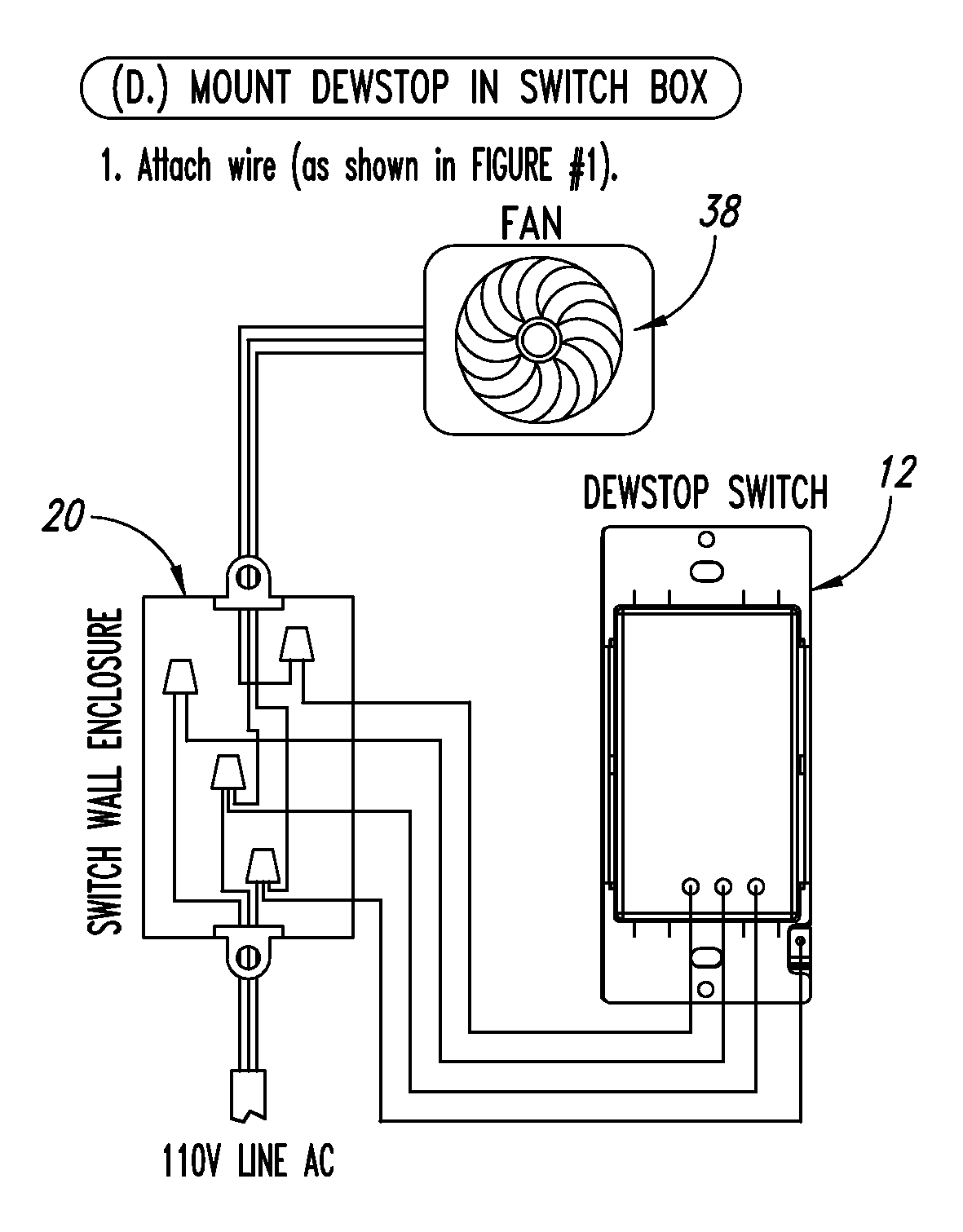
A system and method of controlling a ventilation system is provided based on a determination of local dew point and automatically activating an exhaust fan before condensate appears on structure and objects and ideally before visible condensation forms in the air of an enclosed area. Firmware in the control circuit detects the presence of hardware components 1 and operates a control circuit in one of a plurality of modes based on the detected hardware components that are coupled to the control circuit.

Description

BACKGROUND[0001]1. Technical Field[0002]The present disclosure pertains to the removal of moisture vapor from enclosed areas and, more particularly, to a ventilation system having a controller that controls exhaust fan operation based on relative humidity, temperature, and local dew point determinations in the surrounding air.[0003]2. Description of the Related Art[0004]Moisture vapor, which is the presence of condensed water in the surrounding air, can pose a health risk, and condensate resulting from water in the air can damage or destroy structures, equipment, pharmaceuticals, and food items. Reliable protection against moisture in the air is necessary to properly maintain dry conditions where considerable economic loss may result from a user or maintenance personnel either not switching on an exhaust fan manually or only activating the exhaust for such short times as to be ineffective against the accumulation of both fungal and bacterial growth. Such organisms threaten the healt...

Claims


Application Information

Patent Timeline
Patent Type & Authority Applications(United States)
IPC IPC(8): G05D22/02F24F11/04
CPCF24F11/0001F24F2011/0064F24F11/0015F24F11/0012F24F11/30F24F2110/10F24F2110/20F24F11/65Y10T137/0324F24F11/52F24F11/76F24F11/88F24F11/63F24F11/56
Inventor BRANHAM, TONYERICKSON, CHRISTOPHER
Owner GTR TECH
Why Eureka
Try Eureka