
Apparatus for facilitating circulation

a technology of apparatus and blood circulation, applied in the field of medical devices, can solve the problems of high side effects of blood clotting, cardiac arrest or stroke in patients, and the cost of such a treatment is often in excess of the patient's reasonable budg

Inactive Publication Date: 2013-01-17
MICHIGAN MEDICAL INNOVATIONS
View PDF5 Cites 7 Cited by
  • Summary
  • Abstract
  • Description
  • Claims
  • Application Information

AI Technical Summary

Benefits of technology

The patent is about a method for helping patients to circulate blood by using two leg assemblies that are attached to a pneumatic assembly. The pneumatic assembly is programmed to cycle and hold for a set amount of time, and the treatment is administered to both legs during that time. The method also includes monitoring the temperature and pressure sensors that are attached to the legs to ensure the treatment is going well. This method helps to improve the patient's blood flow and can be used in a variety of medical settings.

Problems solved by technology

Blood clotting is a highly serious side effect of many medical procedures and medical conditions.
A blood clot within the body of a patient can cause a cardiac arrest or a stroke in a patient.
Moreover, as the procedure necessarily requires the use of hospital or clinical facilities, the cost associated with such a treatment is often in excess of that which a patient can reasonably afford.
Other equipment, while transportable, is generally incapable of adjustment or customization.
Specifically, such systems are not able to adjust cycle time, hold time, or other parameters, instead relying on a preprogrammed set of parameters.
Furthermore, much of the available equipment is not capable of sensing conditions at or near the treatment area.
In addition, while pneumatic compression has been shown to be an effective treatment for the prevention of DVT patient compliance to such a treatment has been an ongoing problem.

Method used


Image

  • Apparatus for facilitating circulation
  • Apparatus for facilitating circulation
  • Apparatus for facilitating circulation

Examples


Embodiment Construction

[0040]While this disclosure is susceptible of embodiment in many different forms, there is shown in the drawings and described herein in detail a specific embodiment with the understanding that the present disclosure is to be considered as an exemplification of the principles of the disclosure and is not intended to limit the disclosure to the embodiment illustrated.

[0041]It will be understood that like or analogous elements and / or components, referred to herein, may be identified throughout the drawings by like reference characters. In addition, it will be understood that the drawings are merely schematic representations of the disclosure, and some of the components may have been distorted from actual scale for purposes of pictorial clarity.

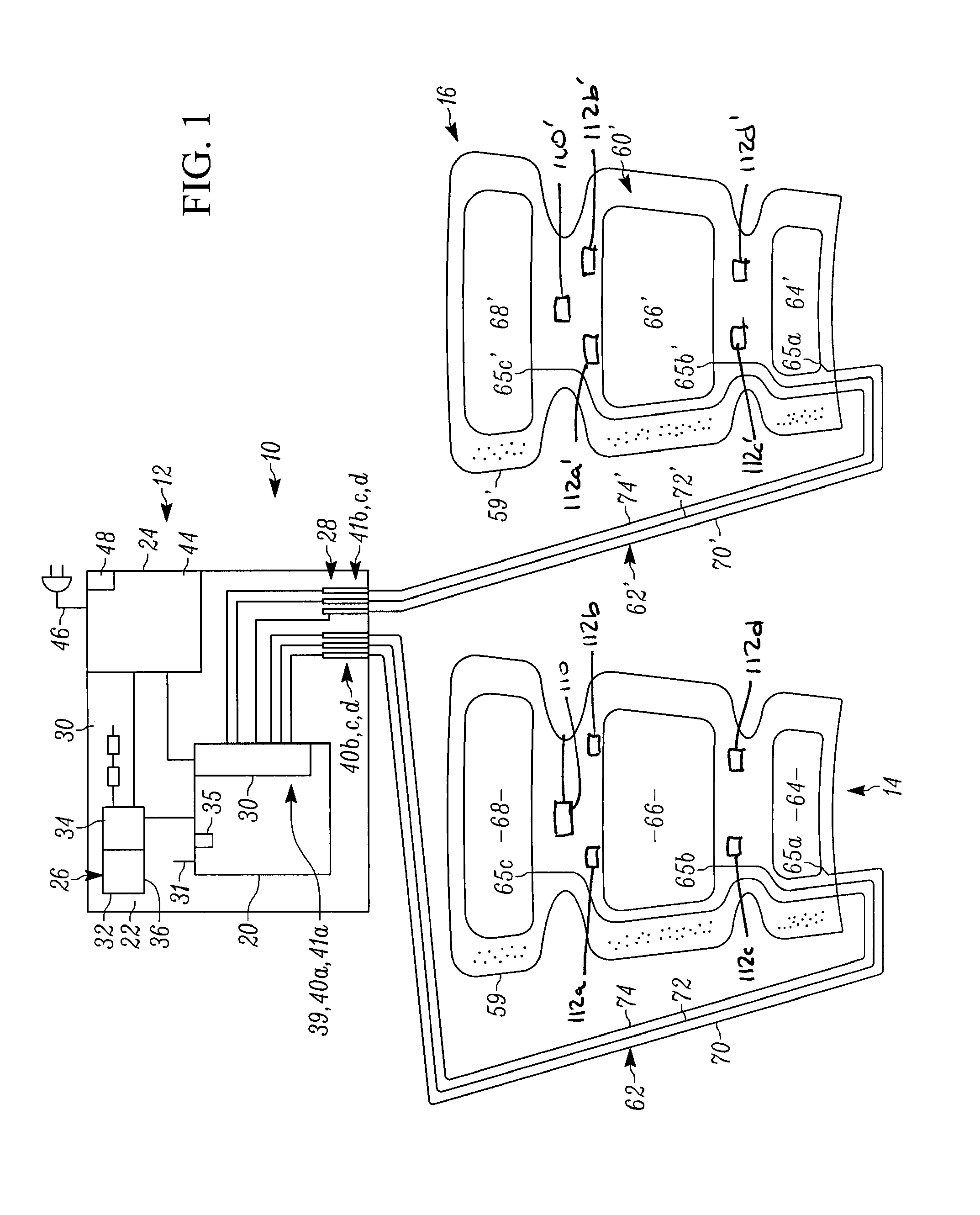
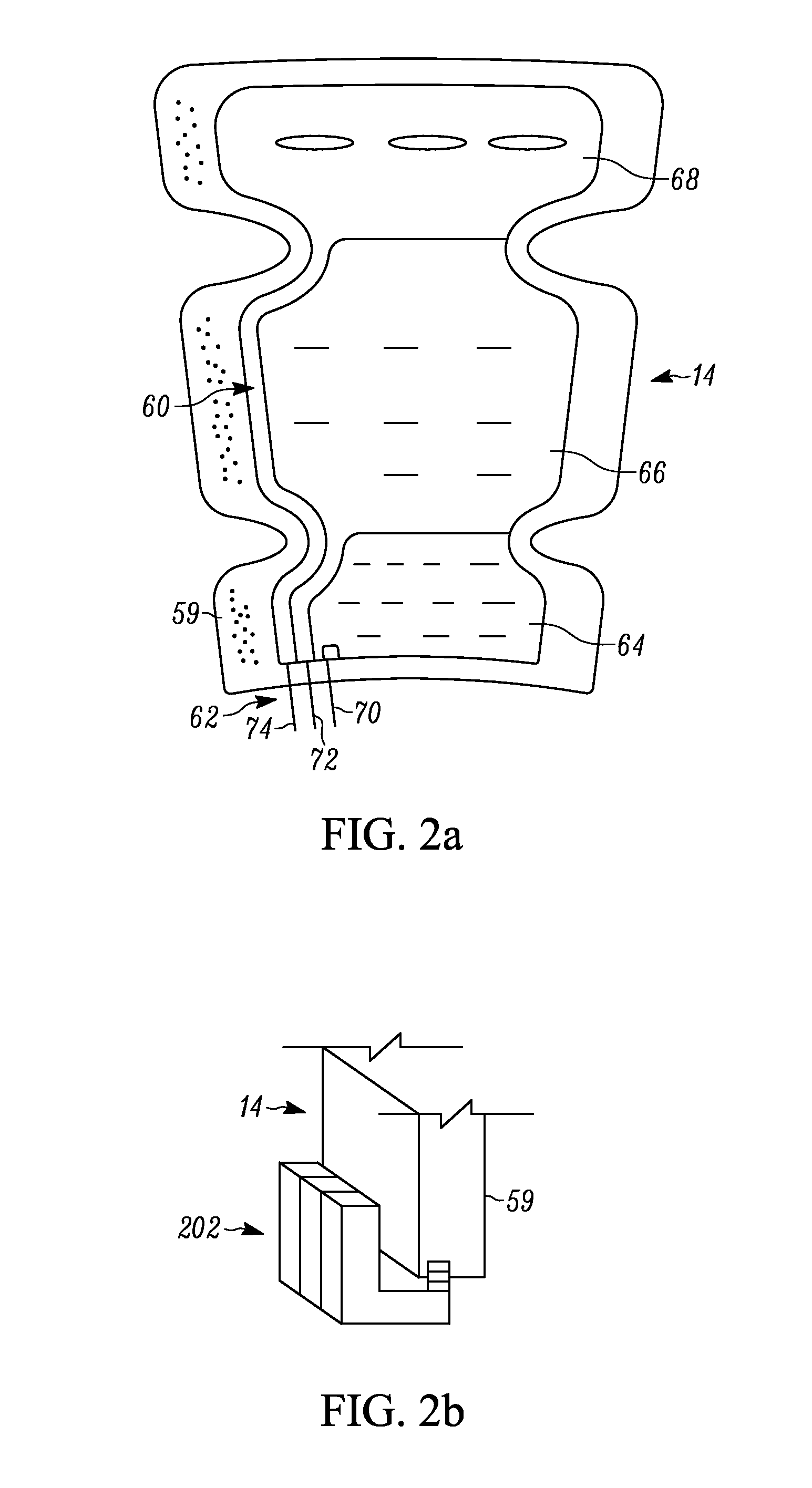
[0042]Referring now to the drawings and in particular to FIG. 1, circulation facilitating apparatus 10 for facilitating circulation of blood within a patient (and, in turn, precluding the clotting of blood) is shown as comprising pneumatic assem...


PUM


Abstract

A circulation facilitating apparatus comprising a pneumatic assembly and first and second leg assemblies. The pneumatic assembly comprises a pump assembly, a control assembly, an air controller assembly and an energizing assembly. The control assembly controls the pump assembly. The control assembly includes a microprocessor and a system for programming the microprocessor. The programming system programs at least a cycle time and at least a hold time. The air controller assembly is coupled to the pump assembly. Each leg assembly includes a bladder, an air passage assembly, a housing, and pulse and / or temperature sensors. A treatment method is likewise disclosed.

Description

CROSS-REFERENCE TO RELATED APPLICATION[0001]This application is related to U.S. patent application Ser. No. 11 / 545,809, entitled Apparatus for Facilitating Circulation, filed Oct. 10, 2006, which claims priority of U.S. Application Ser. No. 60 / 833,707, entitled Apparatus for Facilitating Circulation filed Jul. 27, 2006, to U.S. Application Ser. No. 60 / 724,969 entitled Apparatus for Facilitating Circulation filed Oct. 7, 2005, the entire specification of each is incorporated by reference herein.BACKGROUND OF THE DISCLOSURE[0002]1. Field of the Disclosure[0003]The present disclosure relates in general to medical devices, and in particular, to an apparatus of facilitating the circulation of blood within a patient.[0004]2. Background Art[0005]Blood clotting is a highly serious side effect of many medical procedures and medical conditions. A blood clot within the body of a patient can cause a cardiac arrest or a stroke in a patient. As such, it is highly important to preclude the clottin...

Claims


Application Information

Patent Timeline
IPC IPC(8): A61H7/00
CPCA61G7/0507A61G2203/46A61G7/05776A61H9/0078A61H2201/0142A61H2201/0149A61H2201/0157A61H2201/1642A61H2201/165A61H2201/5002A61H2201/5035A61H2201/5038A61H2201/5046A61H2201/5071A61H2201/5082A61H2205/086A61H2205/10A61H2209/00A61H2230/065A61G2203/10
Inventor KRAAL, ROBERTKULAS, JERRYLINDAHL, JOHN O.
Owner MICHIGAN MEDICAL INNOVATIONS
Learn More