
Passive 3D image system and image processing method thereof

Active Publication Date: 2013-01-10
MEDIATEK INC
View PDF2 Cites 2 Cited by
  • Summary
  • Abstract
  • Description
  • Claims
  • Application Information

AI Technical Summary

Benefits of technology

The present invention provides a passive 3D image system and an image processing method that can increase the luminance of an image to provide enhanced details to a viewer. Compared to a conventional passive 3D image display system, the invention provides an image of better definition. The image processing method is also applicable to hardware having a fixed frame rate and offers better application flexibilities compared to conventional techniques.

Problems solved by technology

However, the active technique suffers from a drawback that, a wireless communication mechanism is necessarily provided at both terminals in order to achieve synchronous switching of the images on the display apparatus and the switching of the 3D glasses.
Thus, the 3D glasses not only cost more but also are bulkier.
In addition, flickers in visual effects are incurred when image data lower than 60 Hz is presented to the human eyes, and further lead to discomfort of the eyes.
In other words, the active display technique is only suitable for display systems supporting up to a frame rate of 120 Hz, and is hence not widely adopted.
The polarizing film is an inexpensive material, and an overall cost of the passive 3D display system is relatively low.
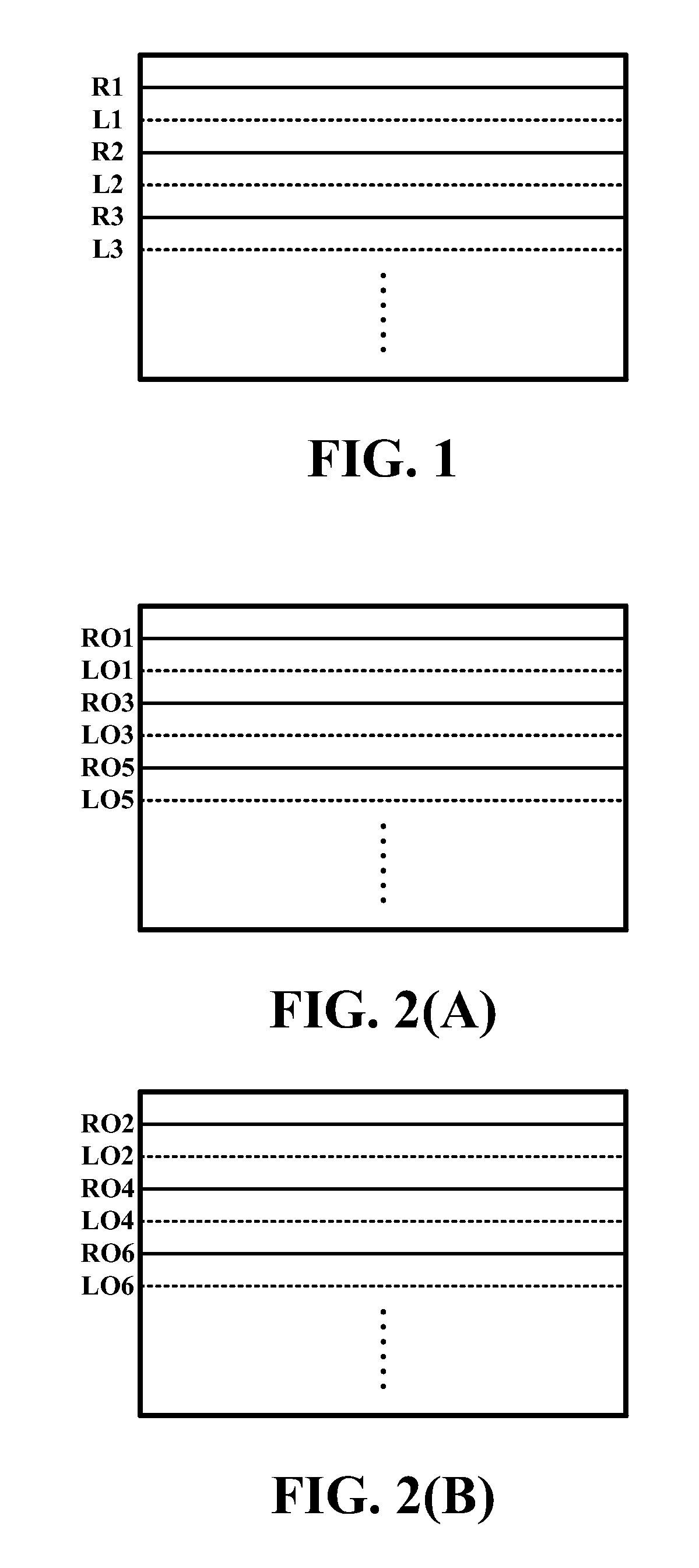
Such approach however also suffers from a drawback that, the horizontal resolution of the images perceived by the left and right eyes of the viewer is only 540 pixels even though the horizontal resolution of the display is 1080, meaning that a data amount of the original image is halved.
As a result, the image may appear as having insufficient luminance, details and clearness to the viewer.
Therefore, the conventional technique shown in FIG. 2A and FIG. 2B is not quite prevalent since it is only suitable for display systems capable of doubling the frame rate to 120 Hz.

Method used


Image

  • Passive 3D image system and image processing method thereof
  • Passive 3D image system and image processing method thereof
  • Passive 3D image system and image processing method thereof

Examples


Embodiment Construction

[0021]The present invention will now be described more specifically with reference to the following embodiments. It is to be noted that the following descriptions of preferred embodiments of this invention are presented herein for purpose of illustration and description only. It is not intended to be exhaustive or to be limited to the precise form disclosed.

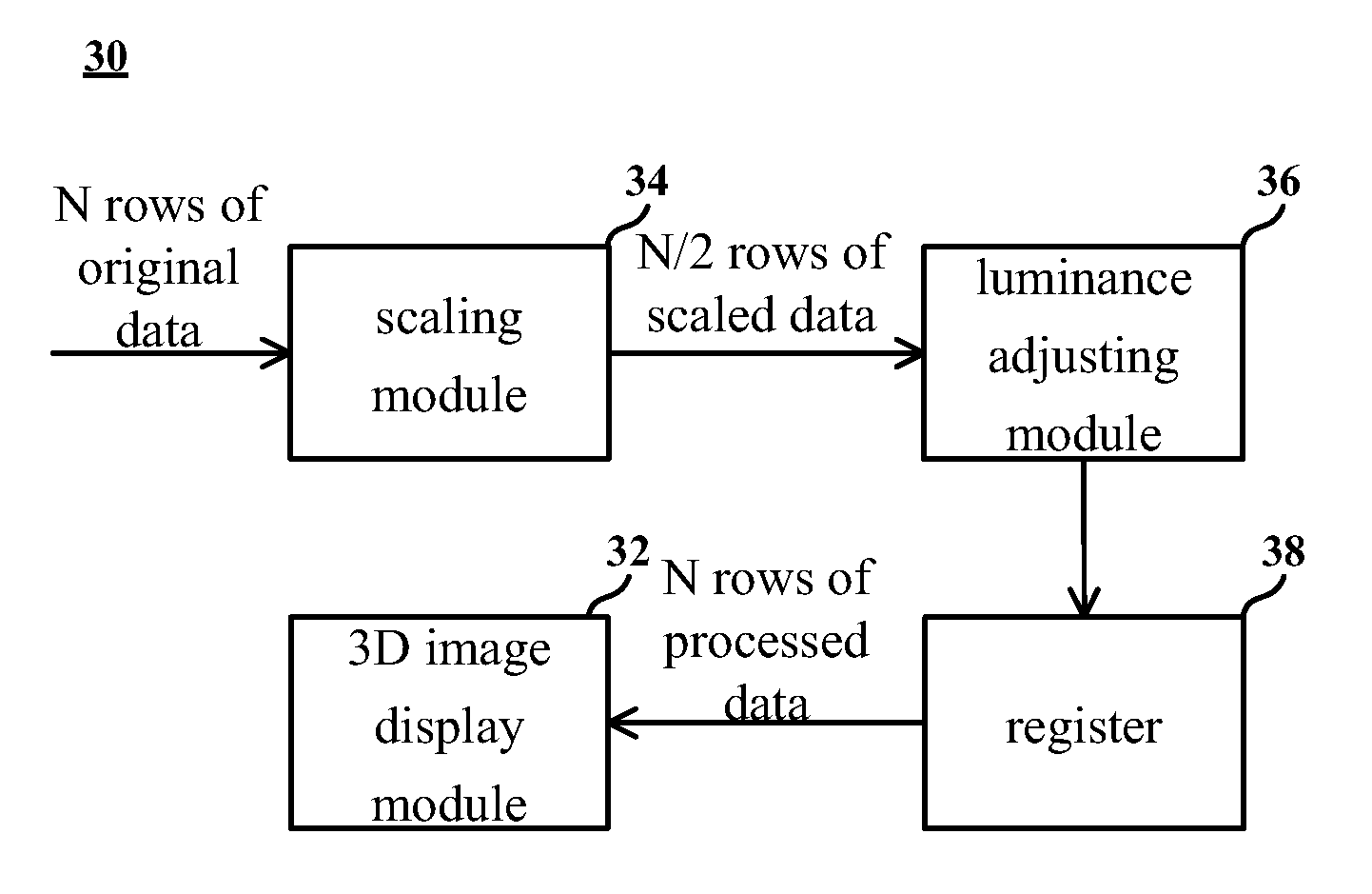
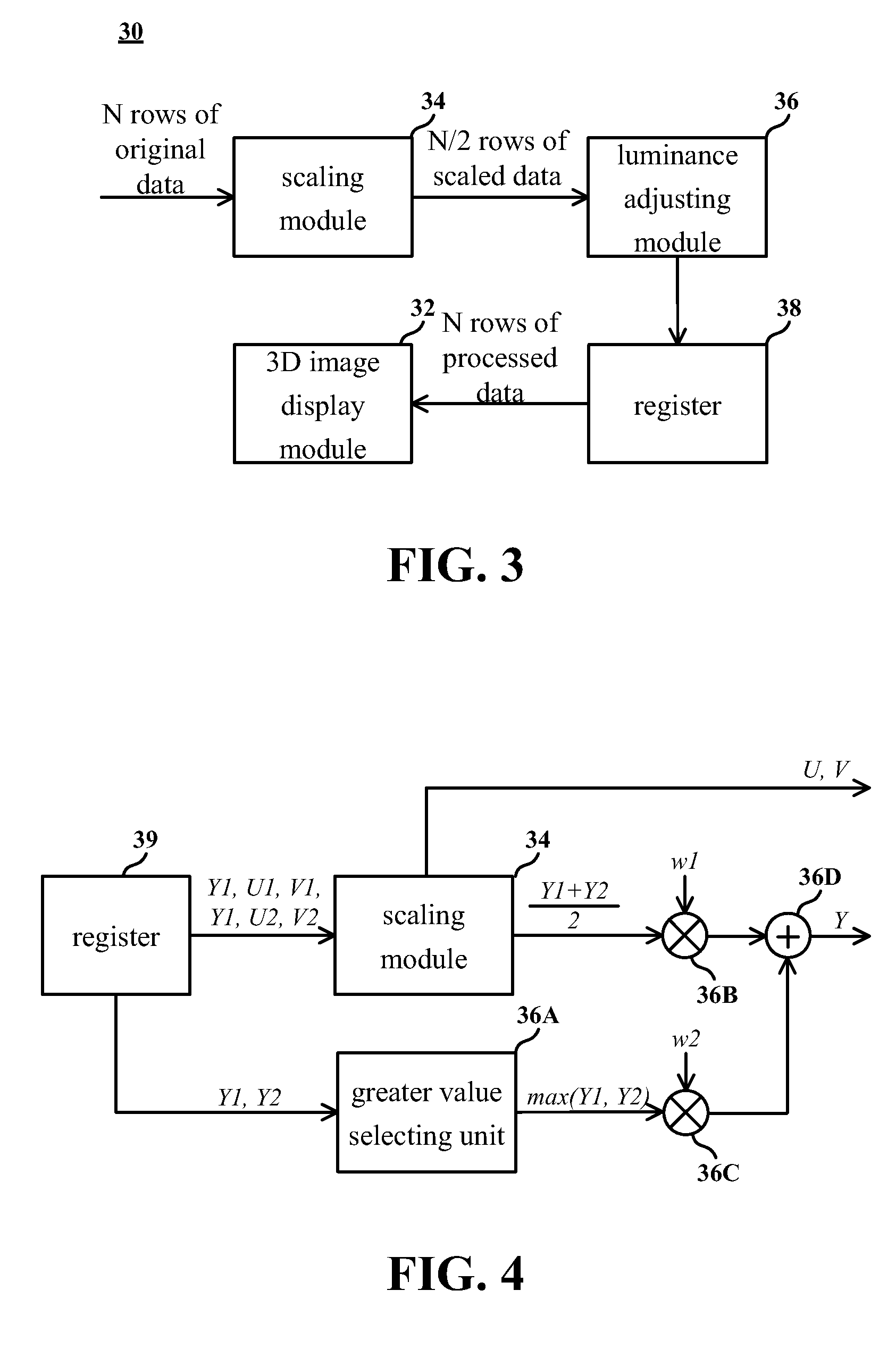
[0022]A passive 3D image system according to an embodiment of the present invention is provided. For example, the system is a household television system or a commercial movie playback system. Referring to FIG. 3, a passive 3D image system 30 comprises a passive 3D image display module 32, a scaling module 34, a luminance adjusting module 36 and a register 38. To focus on the technique of the present invention, other hardware devices such as speakers in the passive 3D image system 30 are not illustrated in the diagram.

[0023]The passive 3D image display module 32 comprises N rows of display units, where N is a positive even intege...


PUM


Abstract

A passive 3D image system including a passive 3D image display apparatus, a scaling module and a luminance adjusting module is provided. The 3D passive image display apparatus includes N rows of display units. After receiving an original image including N rows of original data, the scaling module merges the N rows of original data to generate a scaled image including N / 2 rows of scaled data. The original image is either a left-eye image or a right-eye image. The luminance adjusting module adjusts the N / 2 rows of scaled data to increase the luminance of the scaled image.

Description

FIELD OF THE INVENTION[0001]The present invention relates to an image display system, and more particularly to a technique for enhancing a resolution of 3D images.BACKGROUND OF THE INVENTION[0002]Along with the development of software and hardware techniques, commercial and household 3D display apparatuses become matured and 3D images have also become a great development trend in multimedia. Current 3D image display techniques are in general categorized into active and passive types, which shall be described below.[0003]The active 3D image display technique alternately presents left-eye and right-eye images on a single monitor. Dedicated glasses worn by a viewer shield a right eye of the viewer when a left-eye image is presented and shield a left eye of the viewer when a right-eye image is presented. A visual system of the viewer automatically combines images successively received by the both eyes to 3D images. Due to vision persistence, the brief shielding by the 3D glasses against...

Claims


Application Information

Patent Timeline
IPC IPC(8): G06T15/00
CPCH04N13/0434H04N13/0007H04N13/106H04N13/337
Inventor CHEN, CHUNG-YI
Owner MEDIATEK INC
Learn More