Method and apparatus for self-annealing multi-die interconnect redundancy control

a multi-die interconnect and self-annealing technology, applied in the direction of fault response, semiconductor/solid-state device testing/measurement, instruments, etc., can solve the problems of not being able to ensure not being able to have one or more faulty bumps in a device, and not being able to achieve 100% yield of all bumps

Active Publication Date: 2013-01-10
XILINX INC
View PDF1 Cites 12 Cited by
  • Summary
  • Abstract
  • Description
  • Claims
  • Application Information

AI Technical Summary

Benefits of technology

[0020]In any of the embodiments described herein, the method can further include replacing a functionality of the first μbump with a functionality of the second μbump based at least in part upon one or more values, wherein the one or more values are derived from at least the first redundancy value stored in the first volatile memory and the second redundancy value stored in the second volatile memory.
[0021]In any of the embodiments described herein, the method can further include determining a first power using the master controller, transmitting a first power good signal using the master controller based at least in part upon a first criterion, determining a second power using the slave controller, transmitting a second power good signal using the slave controller based at least in part upon a second criterion, and determining whether to replace a functionality of the first μbump with a functionality of the second μbump based at least in part upon the first power good signal and the second power good signal.

Problems solved by technology

A common multi-die interconnect often includes hundreds of thousands or millions of μbumps between two semiconductor dies, whereas ensuring 100% yield of all the μbumps is unrealistic.
Thus, it is not uncommon to have one or more faulty μbump(s) in a device.
A μbump may also be considered faulty if it is connected to a broken trace, or to a faulty circuit, which prevents the μbump from transmitting and / or receiving signals.
Also, μbumps may fail due to wear and tear over time or due to environmental effects such as those arising from temperature fluctuations.
Thus, a faulty μbump may be due to any failure mode, including but not limited to the examples mentioned previously.
The conventional redundancy techniques give rise to various disadvantages and difficulties.

Method used


Image

  • Method and apparatus for self-annealing multi-die interconnect redundancy control
  • Method and apparatus for self-annealing multi-die interconnect redundancy control
  • Method and apparatus for self-annealing multi-die interconnect redundancy control

Examples


Embodiment Construction

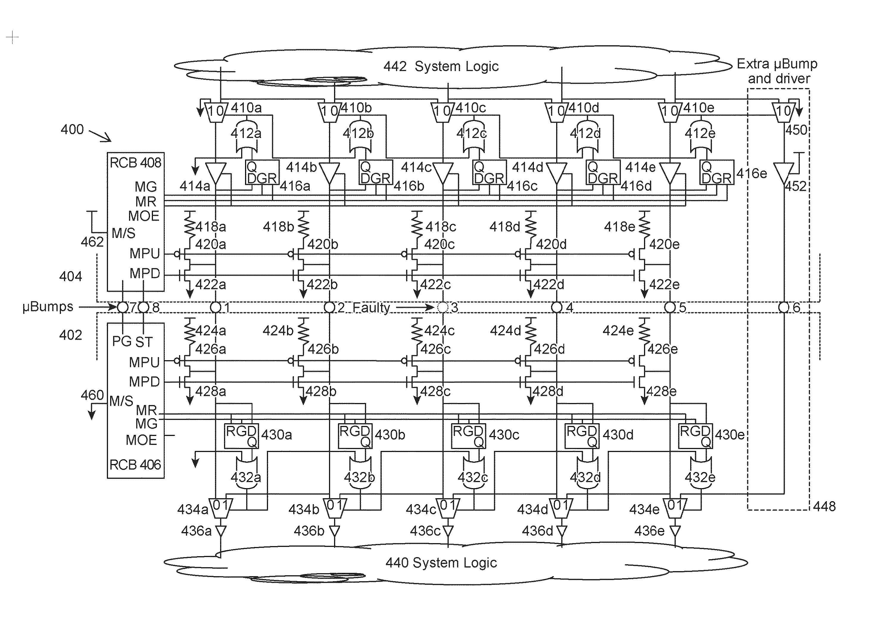
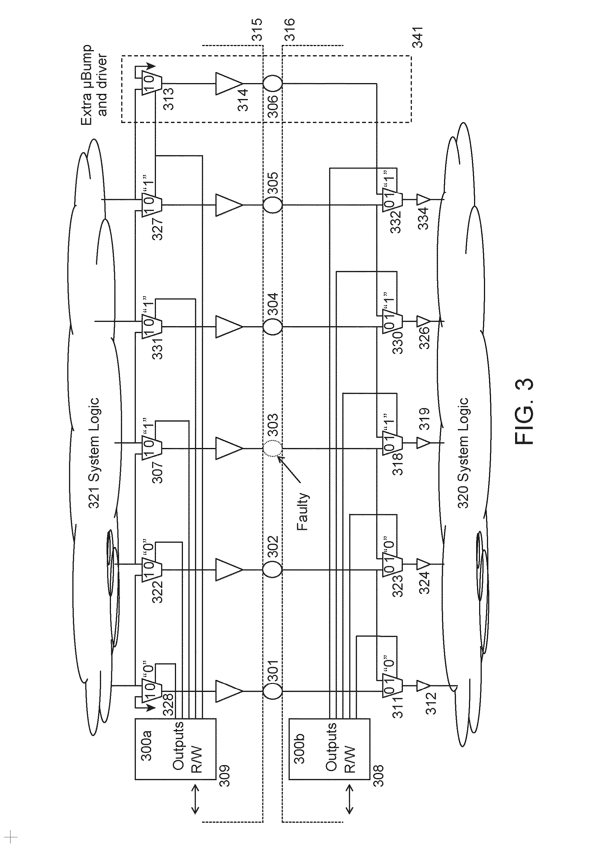
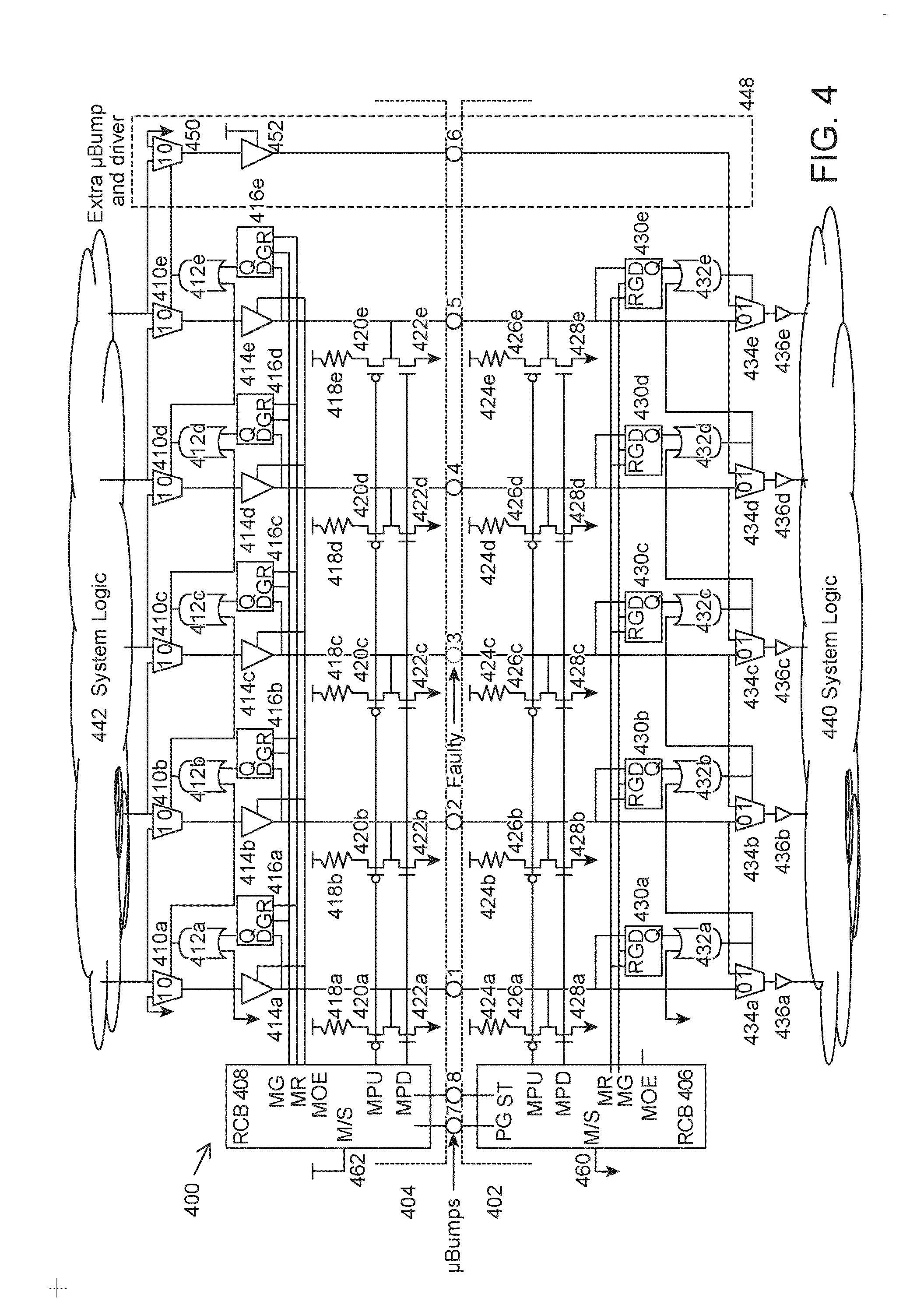
[0052]Various embodiments are described hereinafter with reference to the figures. It should be noted that the figures are not drawn to scale and that elements of similar structures or functions are represented by like reference numerals throughout the figures. It should also be noted that the figures are only intended to facilitate the description of the embodiments. They are not intended as an exhaustive description of the claimed invention or as a limitation on the scope of the claimed invention. In addition, an illustrated embodiment needs not have all the aspects or advantages shown. An aspect or an advantage described in conjunction with a particular embodiment is not necessarily limited to that embodiment and can be practiced in any other embodiments even if not so illustrated. Also, reference throughout this specification to “some embodiments” or “other embodiments” means that a particular feature, structure, material, or characteristic described in connection with the embod...


PUM


Abstract

An apparatus for interconnecting a first die and a second die of a multi-die device includes a master circuit block that interfaces with the first die of the multi-die device, a slave circuit block that interfaces with the second die of the multi-die device, a first memory in the slave circuit block, a second memory in the master circuit block, and a plurality of μbumps between the first die and the second die, wherein the master circuit block and the slave circuit block are configured to identify one of the μbumps as a faulty μbump, and store a first value that corresponds with the identified faulty μbump in the first memory.

Description

TECHNICAL FIELD[0001]Embodiments described herein relate to multi-die interconnect architectures, and in particular, to a method of and apparatus for addressing faulty connections in multi-die interconnect architectures.BACKGROUND[0002]Micro bump structure (μbump) is one of the key technologies in multiple die module (MDM), system in package (SIP), or multi-chip-module (MCM) (hereinafter multi-die interconnect architecture.) A common multi-die interconnect often includes hundreds of thousands or millions of μbumps between two semiconductor dies, whereas ensuring 100% yield of all the μbumps is unrealistic. Thus, it is not uncommon to have one or more faulty μbump(s) in a device.[0003]Examples of a faulty μbump includes but are not limited to: missing μbump, deformation of a μbump, an under-sized μbump, a partially formed μbump, or damaged μbump (e.g., cracked or broken μbump), wherein each of these may result in an open connection. A μbump may also be considered faulty if it is conn...

Claims


Application Information

Patent Timeline
Patent Type & Authority Applications(United States)
IPC IPC(8): G06F11/16
CPCH01L22/22H01L24/14H03K19/00392H01L2224/14515H01L22/14H01L2224/16145H03K19/177H01L22/00H03K19/003
Inventor CAMAROTA, RAFAEL C.
Owner XILINX INC
Why Eureka
Try Eureka