Structure for front foot portion of upper of shoe

a technology for front feet and uppers, which is applied in the direction of uppers, bootlegs, stiffners, etc., can solve the problems of affecting the conformability of the foot, the difficulty of achieving both the holding of the front foot portion by the upper and the foot-fitting property

Active Publication Date: 2013-01-10
ASICS CORP
View PDF30 Cites 26 Cited by
  • Summary
  • Abstract
  • Description
  • Claims
  • Application Information

AI Technical Summary

Benefits of technology

[0022]Before describing the advantageous effects of the present invention, the principles of the present invention will be described.
[0023]FIG. 8 is a side view showing the change in the shape of the foot F when pushing off in the forward direction Y1.
[0024]As shown in FIG. 8, when pushing off in the forward direction, the foot sole significantly bends at the metatarsal phalangeal joint (hereinafter referred to as the “MP joint”).
[0025]In this process, the foot sole is in contact with the ground across the area of the heads of the first to third metatarsal bones and the tips of the toes anterior thereto, including the ball O1 of the big toe (first toe) posterior to the MP joint. On the other hand, the upper surface of the tips of the toes of the foot is bent in the vicinity of the MP joint which is anterior Y1 to the ball O1 of the big toe.
[0026]Thus, the bending position of the upper surface of the front foot portion of the foot is different from the bending position of the foot sole. On the other hand, it is not possible to avoid a difference between how the upper surface of the foot is bent and how the upper is bent. In view of this, we examined the relationship between the upper and the upper surface of the front foot portion of the foot when the foot is bent, by a procedure described below.
[0027]The results of examining the compressive feel to the foot from the upper when it is bent will be discussed using FIGS. 9A and 9B.

Problems solved by technology

However, with the techniques of the patent documents identified above, it will be difficult to realize both the holding of the front foot portion by the upper and a foot-fitting property (conformability) with little compressive feel when it is bent.

Method used


Image

  • Structure for front foot portion of upper of shoe
  • Structure for front foot portion of upper of shoe
  • Structure for front foot portion of upper of shoe

Examples


example 1

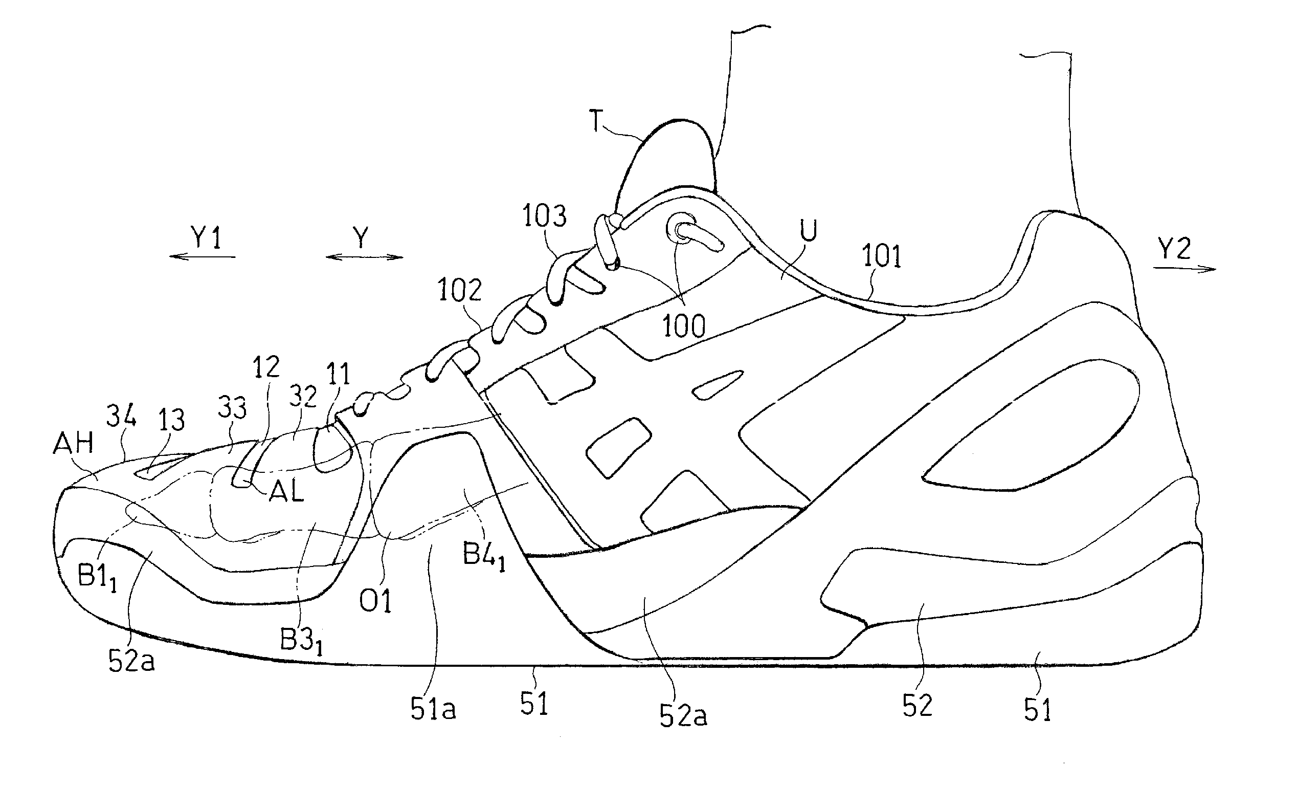
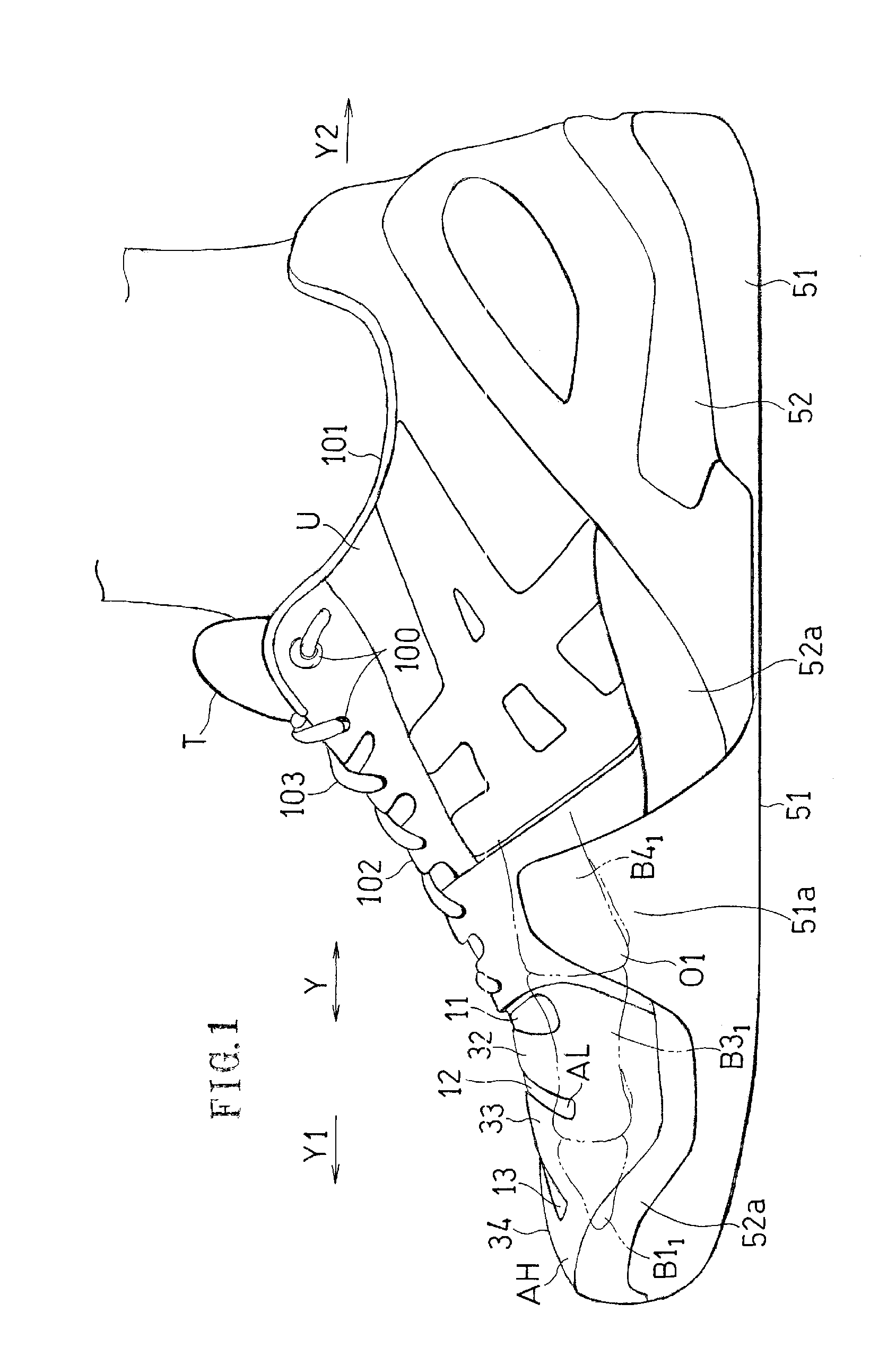
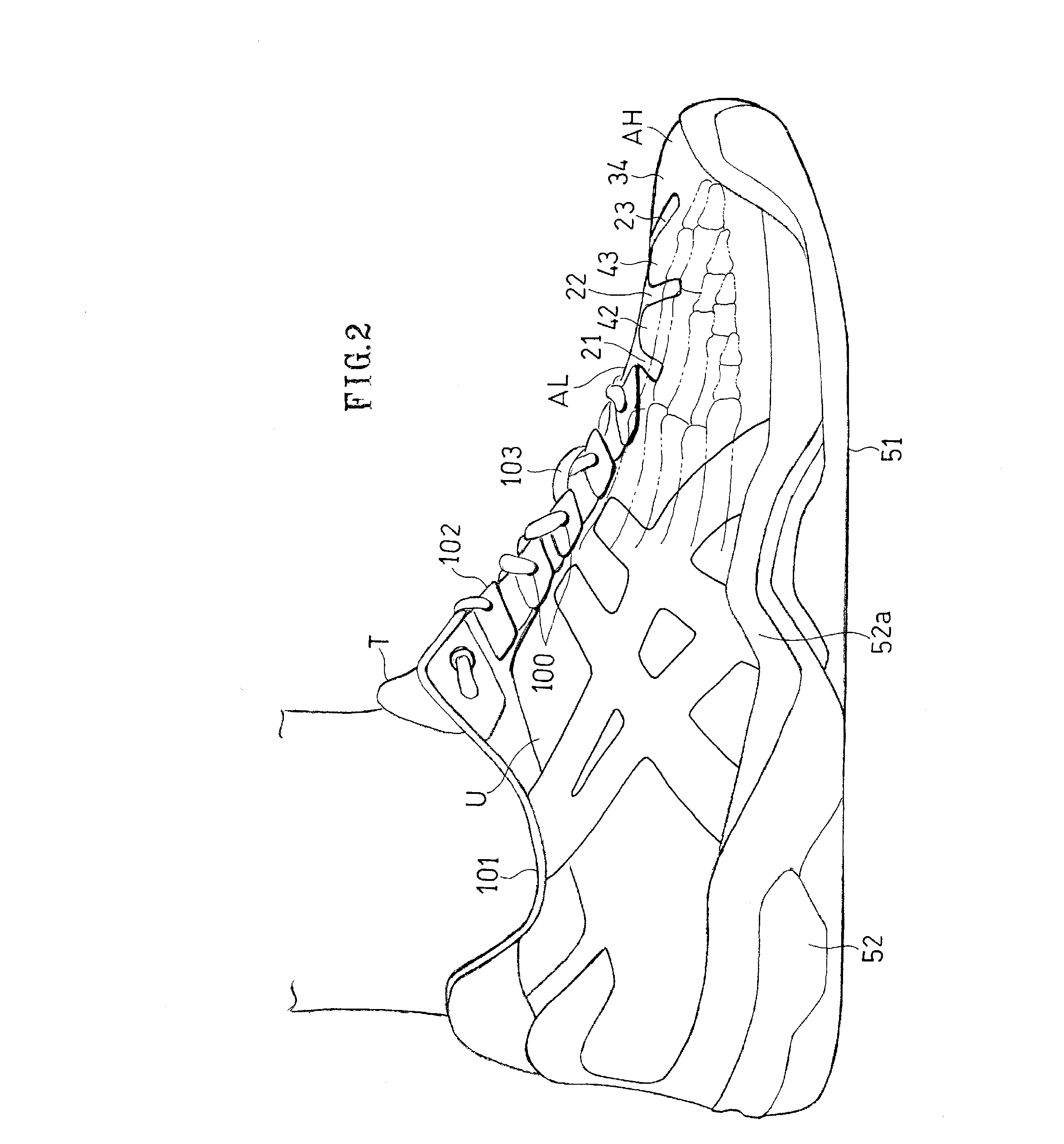
[0108]FIGS. 1 to 7 show a shoe (for right foot) of Example 1.

[0109]In the following examples, IN denotes the medial side of the foot, and OUT denotes the lateral side of the foot.

[0110]As shown in FIG. 1, the shoe of this example includes soles 51 and 52 for absorbing the shock upon landing, and the upper U for wrapping around the instep. The soles are for supporting the foot sole, and include the outer sole 51 and the mid sole 52. As shown in FIG. 1, the upper U is provided with a plurality of insertion holes 100 such as eyelet holes.

[0111]The upper U fits to the instep by fastening a shoe lace 103 (an example of the fastening member) passed through these insertion holes 100.

[0112]As shown in FIG. 1, the upper U includes a first opening 101 through which a leg comes out in an upward direction when worn, and a second opening 102 located anterior Y1 to the first opening 101 and is closed by the tongue T. The first and second openings 101 and 102 are continuous with each other in the ...


PUM

PropertyMeasurementUnit
widthaaaaaaaaaa
widthaaaaaaaaaa
lengthaaaaaaaaaa

Abstract

A low rigidity region being more stretchable and bendable than a high rigidity region, includes a main portion, and a medial first flexible portion and a lateral first flexible portion extending from the main portion in the medial and lateral directions. The main portion covers a portion of the area from the shaft of the first proximal phalanx to the shaft of the second proximal phalanx, the medial first flexible portion covers a portion of the area from the shaft of the first proximal phalanx to the head of the first metatarsal bone, and the lateral first flexible portion extends to the lateral side of the foot from the main portion. When pushing off the foot onto the medial / lateral side in a diagonally forward direction, the upper bends along the diagonal bend lines. Therefore, the diagonal portions and the main portion serve as the bend lines.

Description

CROSS-REFERENCE TO RELATED APPLICATIONS[0001]This application is a continuation in part of the PCT international application No. PCT / JP2010 / 56875 filed on Apr. 16, 2010. The entire content of the international application is hereby incorporated herein by reference.TECHNICAL FIELD[0002]The present invention relates to an improved structure for a front foot portion of an upper of a shoe.BACKGROUND ART[0003]In on-court sports such as tennis, volleyball, and basketball, involving rapid movements forward, backward, left and right, a sport shoe needs to hold the front foot portion by an upper skin in order to prevent injuries in the foot portion. Therefore, the material of an upper skin is required to be non-stretchable and have a high strength. An upper skin is often reinforced with artificial leather, synthetic leather or a belt.[0004]Such an upper skin has a high rigidity. Therefore, the upper skin less easily fits to the foot. For example, when raising the heel portion as is done freq...

Claims


Application Information

Patent Timeline
Patent Type & Authority Applications(United States)
IPC IPC(8): A43B23/02
CPCA43B23/0255A43B23/027A43B23/081A43B23/0235A43B23/0275A43B23/0245
Inventor NISHIWAKI, TSUYOSHIMATSUO, KOUKIMORIYASU, KENTAYANO, SEIJIFURUISHI, RENA
Owner ASICS CORP
Why Eureka
Try Eureka