Camera distance measurement device
a technology of distance measurement and camera, which is applied in the direction of distance measurement, instruments, television systems, etc., can solve the problem of temporal displacement of objects
- Summary
- Abstract
- Description
- Claims
- Application Information
AI Technical Summary
Benefits of technology
Problems solved by technology
Method used
Image

Examples
embodiment 1
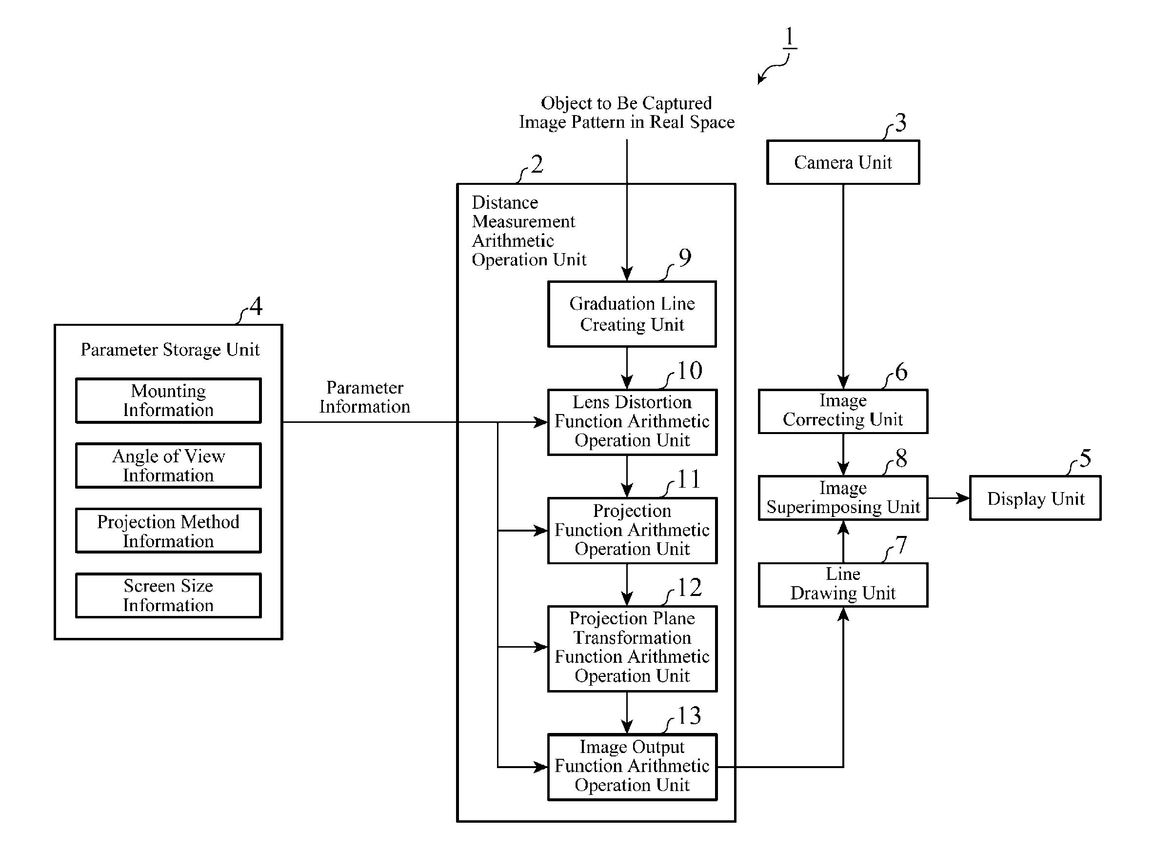
[0017]FIG. 1 is a block diagram showing the structure of a camera distance measurement device in accordance with Embodiment 1 of the present invention. Referring to FIG. 1, the camera distance measurement device 1 is provided with a distance measurement arithmetic operation unit 2, a camera unit 3, a parameter storage unit 4, a display unit 5, an image correcting unit 6, a line drawing unit 7, and an image superimposing unit 8. The distance measurement arithmetic operation unit 2 is a component for calculating a graduation line image showing a distance from a vehicle, and is provided with a graduation line creating unit 9, a lens distortion function arithmetic operation unit 10, a projection function arithmetic operation unit 11, a projection plane transformation function arithmetic operation unit 12, and an image output function arithmetic operation unit 13.
[0018]The camera unit 3 includes a camera for capturing an image of an area surrounding the vehicle (for example, an area behi...
embodiment 2
[0036]FIG. 5 is a block diagram showing the structure of a camera distance measurement device in accordance with Embodiment 2 of the present invention. Referring to FIG. 5, the camera distance measurement device 1A is provided with a distance measurement arithmetic operation unit 2A, a camera unit 3, a parameter storage unit 4, an output unit 5A, and an in-screen position determining unit 14. The distance measurement arithmetic operation unit 2A is a component for transforming an arbitrary coordinate position in a camera image which is specified by the in-screen position determining unit 14 into a position on a ground surface in real space to calculate the distance from a vehicle to the position, and is provided with a lens distortion function arithmetic operation unit 10, a projection function arithmetic operation unit 11, a projection plane transformation function arithmetic operation unit 12, and an image output function arithmetic operation unit 13.
[0037]The output unit 5A is a ...
embodiment 3
[0046]In Embodiment 3, a structure having a combination of those according to above-mentioned Embodiments 1 and 2 will be shown. FIG. 6 is a block diagram showing the structure of a camera distance measurement device in accordance with Embodiment 3 of the present invention. Referring to FIG. 6, the camera distance measurement device 1B has a structure which is a combination of those shown in FIGS. 1 and 2. While the camera distance measurement device displays a graduation line image on a display unit 5, like that according to above-mentioned Embodiment 1, the camera distance measurement device determines an arbitrary position in the graduation line image by using an in-screen position determining unit 14, and transforms the arbitrary position to a coordinate position at a height of z in real space (e.g. the height from a ground surface to a camera), like that according to above-mentioned Embodiment 2.
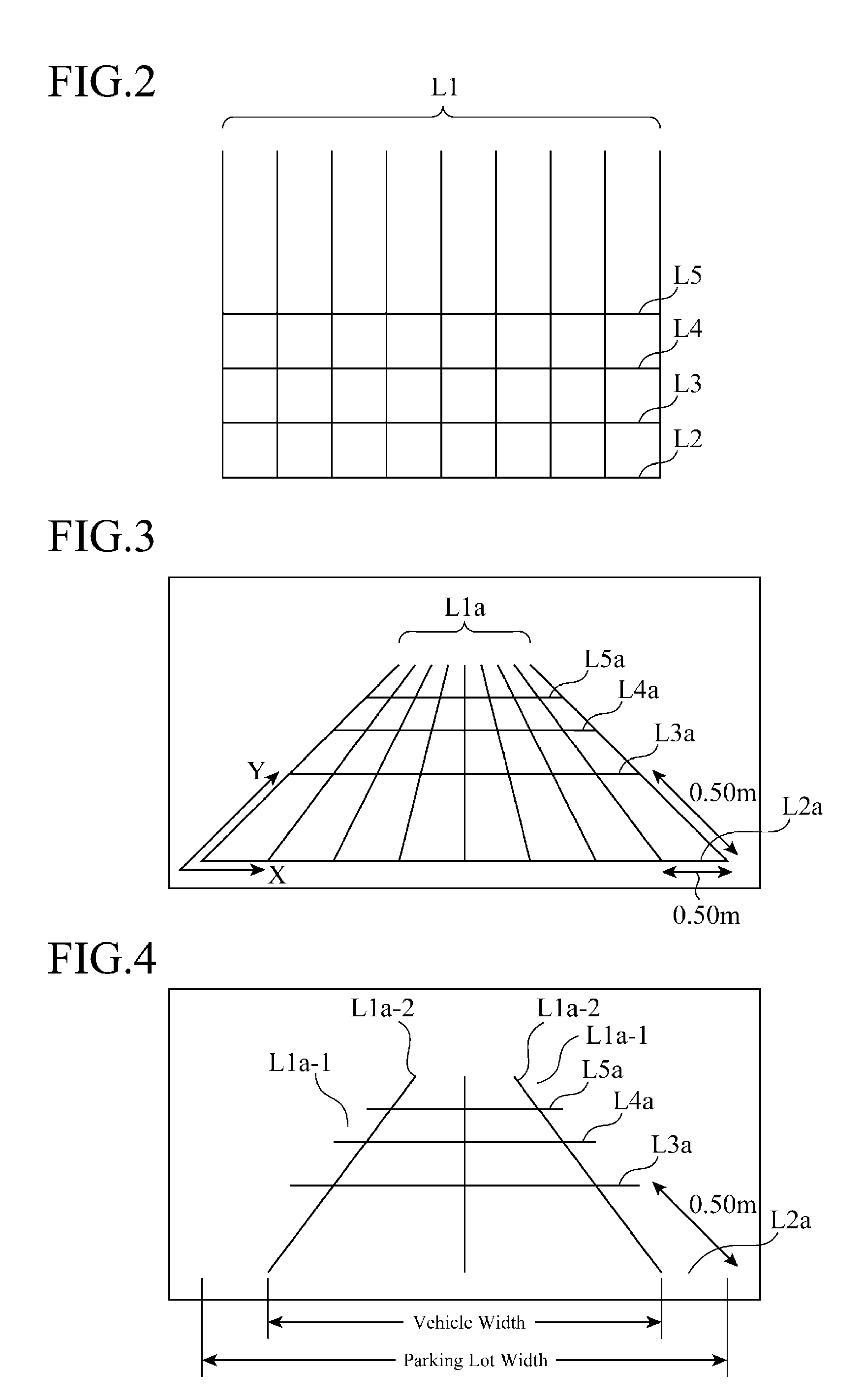
[0047]FIG. 7 is a view showing an example of the graduation line image in accordanc...
PUM
 Abstract
Description
Claims
Application Information
 - R&D
- Intellectual Property
- Life Sciences
- Materials
- Tech Scout
- Unparalleled Data Quality
- Higher Quality Content
- 60% Fewer Hallucinations
Browse by: Latest US Patents, China's latest patents, Technical Efficacy Thesaurus, Application Domain, Technology Topic, Popular Technical Reports.
© 2025 PatSnap. All rights reserved.Legal|Privacy policy|Modern Slavery Act Transparency Statement|Sitemap|About US| Contact US: help@patsnap.com