
Anchor bolt template

a template and anchor bolt technology, applied in the field of anchor bolt templates, can solve the problems of time-consuming and difficult repositioning of anchor bolts, and achieve the effect of facilitating simultaneous positioning and facilitating efficient installation and anchoring of the associated vertical structur

Inactive Publication Date: 2012-12-27
VRAME PETER A
View PDF2 Cites 27 Cited by
  • Summary
  • Abstract
  • Description
  • Claims
  • Application Information

AI Technical Summary

Benefits of technology

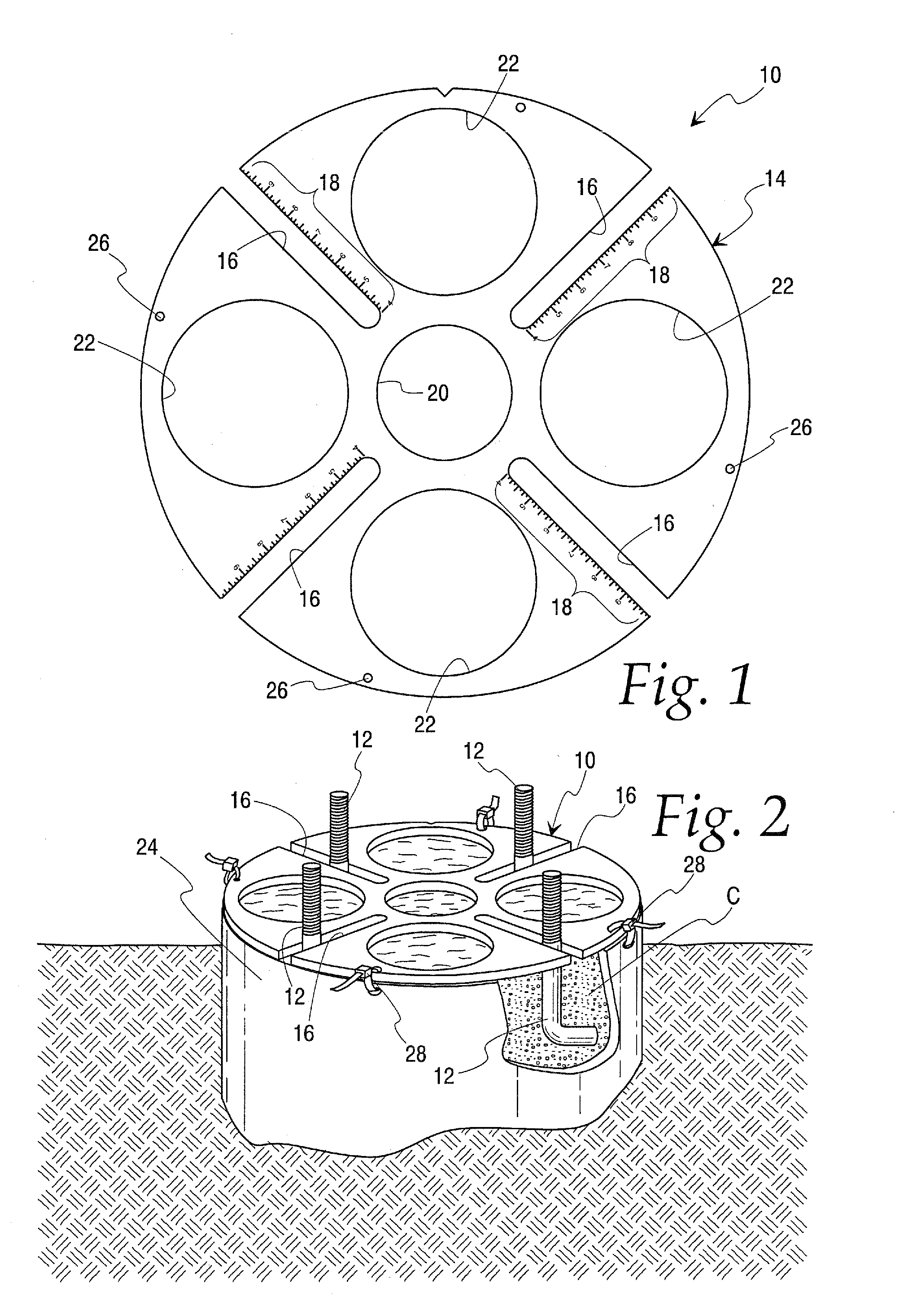
"The present invention provides a reusable anchor bolt template for efficient and simultaneous positioning of multiple anchor bolts in operative association with anchoring material such as concrete or the like. The template is designed to be used with a cylindrical tube for containing and confining the anchoring material. The template includes a body with a plurality of bolt-receiving channels, with bolt-positioning indicia on the upper surface of the template body to facilitate positioning of the anchor bolts. The template can be simultaneously positioned on top of the cylindrical tube and secured in place using securement elements such as zip ties or the like. The openings in the template body allow for the introduction of anchoring material through the template and into the cylindrical tube to anchor the anchor bolts. The invention provides a more efficient and streamlined method for anchoring vertical structures, reducing installation time and facilitating the attachment of the vertical structure to the anchor bolts."

Problems solved by technology

Positioning of the anchor bolts in this matter can be time consuming, since the anchor bolts must be accurately positioned for securely anchoring the associated vertical structure.
As will be appreciated, repositioning of the anchor bolts cannot be easily affected after the concrete hardens, thus mandating precise positioning of the anchor bolts.

Method used


Image

  • Anchor bolt template
  • Anchor bolt template
  • Anchor bolt template

Examples


Embodiment Construction

[0019]While the present invention is susceptible of embodiment in various forms, there is shown in the drawings, and will hereinafter be described, presently preferred embodiments, with the understanding that the present disclosure is to be considered as an exemplification of the invention, and is not intended to limit the invention to the specific embodiment illustrated.

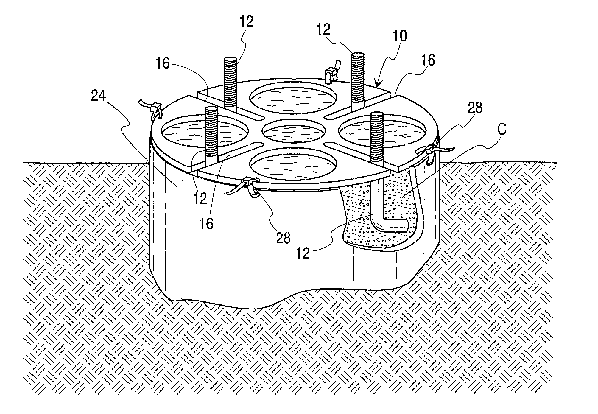
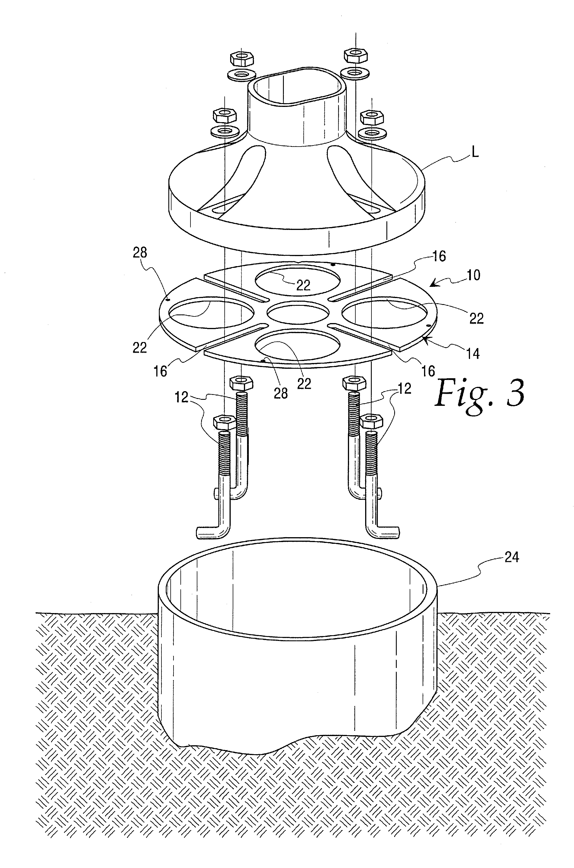
[0020]With reference now to FIGS. 1-3, therein is illustrated an anchor bolt template 10 embodying the principles of the present invention. As will be further described, anchor bolt template 10 facilitates efficient, simultaneous positioning of a plurality of associated anchor bolts 12 in associated anchoring material, such as concrete. The anchoring structure thus formed facilitates secure and stable anchoring of an associated vertical structure, such as a lamp post or the like, or other anchored structure.

[0021]In accordance with the illustrated embodiment, the anchor bolt template 10 includes a generally planar t...


PUM


Abstract

A reusable anchor bolt template facilitates positioning of anchor bolts in anchoring material such as concrete, for subsequent mounting of a vertical structure, such as a light pole or the like. The anchor bolt template comprises a template body which defines a plurality of bolt-receiving channels within which the anchor bolts are respectfully positioned. By this arrangement, the template and anchor bolt can be positioned, as an assembly or unit, on an associated cylindrical tube or like structure which contains and confines the associated anchoring material. The template can be configured to permit the introduction of the anchoring material generally to the template, with the template thereafter being removable, and reused, if desired.

Description

TECHNICAL FIELD[0001]The present invention relates generally to an arrangement to facilitate installation of a vertical structure, such as a light pole or post, and more particularly to a reusable anchor bolt template configured to receive a plurality of associated anchor bolts, and facilitate simultaneous positioning of the template and the anchor bolts, as an assembly, for subsequent introduction of anchoring material, such as concrete or the like.BACKGROUND ART[0002]Installation of vertical structures, such as light poles or posts, ordinarily entails the provision of a suitable anchoring structure, such as a mass of concrete or like material. To facilitate secure mounting of the vertical structure, a plurality of suitable anchor bolts, or like mechanical fasteners, are typically embedded in the anchoring material. The vertical structure can then be secured to the anchor bolts, whereby the structure is securely and stably mounted in the desired vertical orientation.[0003]Heretofor...

Claims


Application Information

Patent Timeline
Patent Type & Authority Applications(United States)
IPC IPC(8): E04B1/38G01B3/14
CPCE04G21/185E04H12/2253
Inventor VRAME, PETER A.
Owner VRAME PETER A
Learn More