
Seismic imaging method considering a contour of the sea bottom

a seismic imaging and contour technology, applied in the direction of instruments, digital data processing details, computation using non-denominational number representations, etc., can solve the problems of inaccurate estimation of signals reflected or transmitted through the sea bottom, and accurately reflect more detailed contours of the sea bottom. , the effect of reducing computational overburden

Inactive Publication Date: 2012-12-20
SEOUL NAT UNIV R&DB FOUND
View PDF6 Cites 4 Cited by
  • Summary
  • Abstract
  • Description
  • Claims
  • Application Information

AI Technical Summary

Benefits of technology

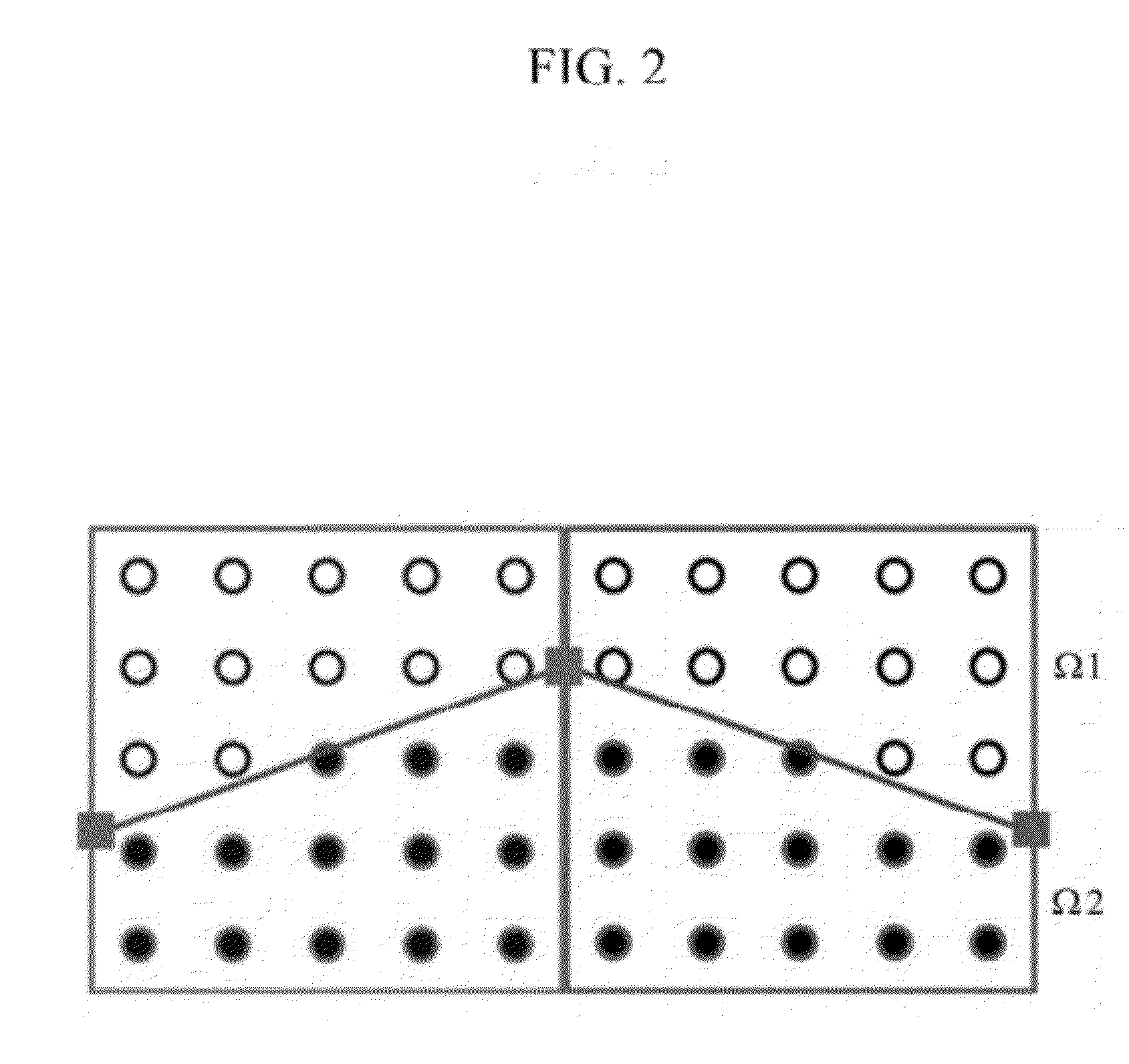
"The patent describes a method for accurately estimating signals reflected on or transmitted through the sea bottom by calculating a coefficient matrix of a wave equation according to a contour of the sea bottom within a global grid. This method minimizes computational overburden and accurately reflects more detailed contours of the sea bottom. The method involves applying a numerical integration method to two domains, the first domain being an upper medium above the sea bottom and the second domain being a lower medium below the sea bottom. The numerical integration method used is Gaussian Quadrature Integration Method."

Problems solved by technology

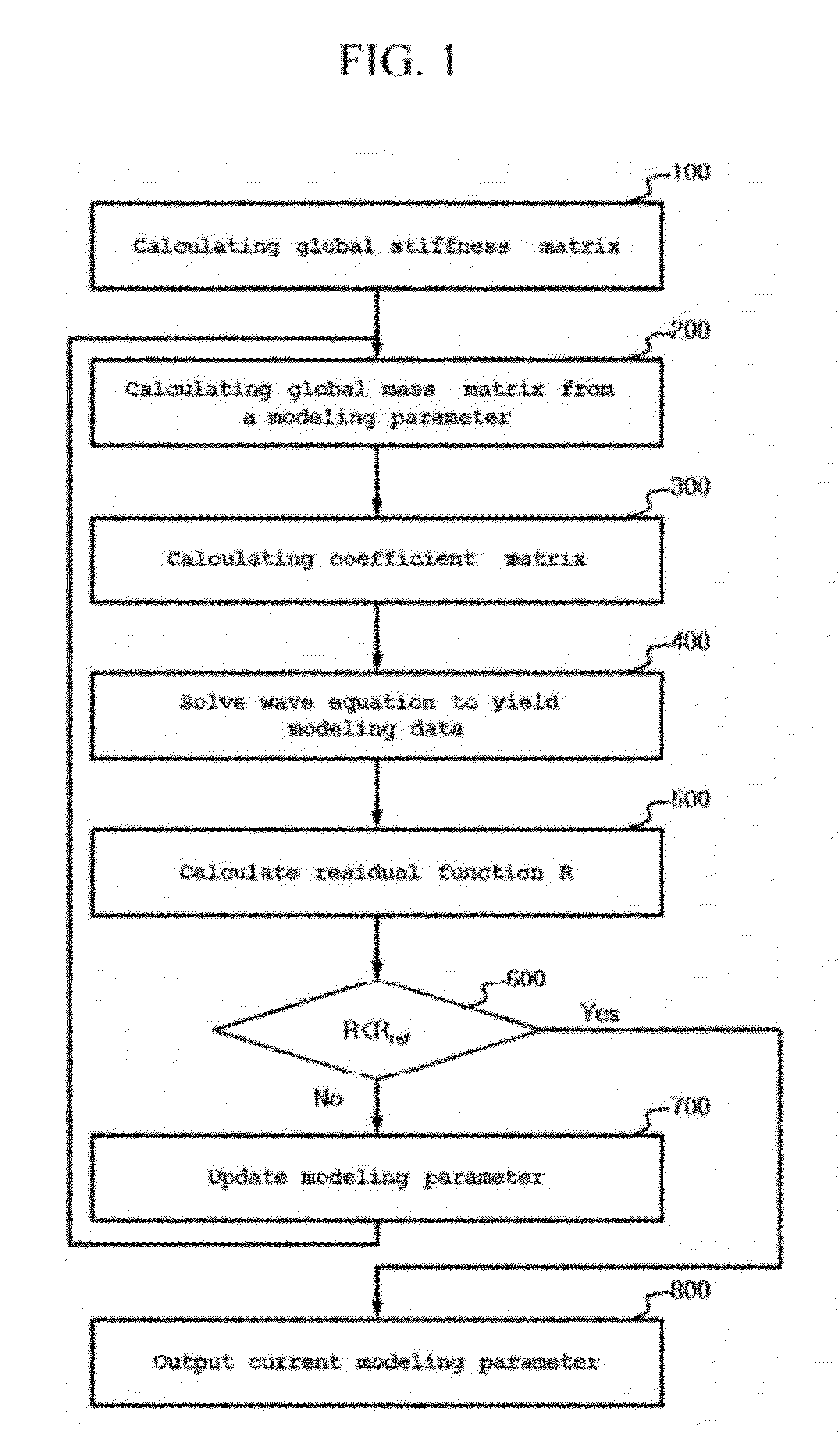
This resulted in inaccurate estimation of signals reflected on or transmitted through the sea bottom.

Method used


Image

  • Seismic imaging method considering a contour of the sea bottom
  • Seismic imaging method considering a contour of the sea bottom
  • Seismic imaging method considering a contour of the sea bottom

Examples


Embodiment Construction

[0014]The following description is provided to assist the reader in gaining a comprehensive understanding of the methods, apparatuses, and / or systems described herein. Accordingly, various changes, modifications, and equivalents of the methods, apparatuses, and / or systems described herein will be suggested to those of ordinary skill in the art. Also, descriptions of well-known functions and constructions may be omitted for increased clarity and conciseness.

[0015]An example of a seismic imaging method includes waveform inversion. According to an aspect, an embodiment of the waveform inversion obtains a modeling parameter for a wave equation by updating the modeling parameter iteratively in the direction of minimizing a residual function regarding an error between modeling data and measured data, wherein the modeling data is a solution of the wave equation to which a coefficient matrix obtained from the modeling parameter has been applied, and the measured data has been measured by a ...


PUM


Abstract

A seismic imaging method for imaging a subsurface structure is provided. The seismic imaging method calculates a coefficient matrix of a wave equation according to a contour of the sea bottom within a global grid. This method can be used to accurately estimate signals reflected on or transmitted through the sea bottom because it accurately reflects more detailed contours of the sea bottom within the global grid. Moreover, computational overburden is minimized.

Description

CROSS-REFERENCE TO RELATED APPLICATION[0001]This application claims the benefit under 35 U.S.C. §119(a) of a U.S. Patent Application No. 61 / 496790, filed on Jun. 14, 2011, and a Korean Patent Application No. 10-2012-0063898, filed on Jun. 14, 2012,the entire disclosure of which is incorporated herein by reference for all purposes.BACKGROUND[0002]1. Field[0003]The following description relates to a seismic imaging technology for imaging a subsurface structure by processing measured data reflected from the subsurface structure after a wave from a source wave has been propagated to the subsurface structure.[0004]2. Description of the Related Art[0005]Technologies for imaging a subsurface structure through waveform inversion have been studied and developed. An example of such technologies is disclosed in a Korean Patent Registration No. 1,092,668 registered on Dec. 5, 2011, filed on Jun. 17, 2009 with the Korea Intellectual Property Office. The Korean Patent Registration has been filed ...

Claims


Application Information

Patent Timeline
Patent Type & Authority Applications(United States)
IPC IPC(8): G06F17/11G06F17/16G06F17/10
CPCG01V1/301
Inventor SHIN, CHANGSOO
Owner SEOUL NAT UNIV R&DB FOUND
Learn More