Efficient bias power supply for non-isolated dc/dc power conversion applications

a power supply and non-isolation technology, applied in the direction of electric variable regulation, process and machine control, instruments, etc., can solve the problem of significant power efficiency loss

Inactive Publication Date: 2012-12-13
HUDA MUZAHID BIN
View PDF1 Cites 5 Cited by
  • Summary
  • Abstract
  • Description
  • Claims
  • Application Information

AI Technical Summary

Problems solved by technology

This causes significant loss in power efficiency.

Method used


Image

  • Efficient bias power supply for non-isolated dc/dc power conversion applications
  • Efficient bias power supply for non-isolated dc/dc power conversion applications
  • Efficient bias power supply for non-isolated dc/dc power conversion applications

Examples


second embodiment

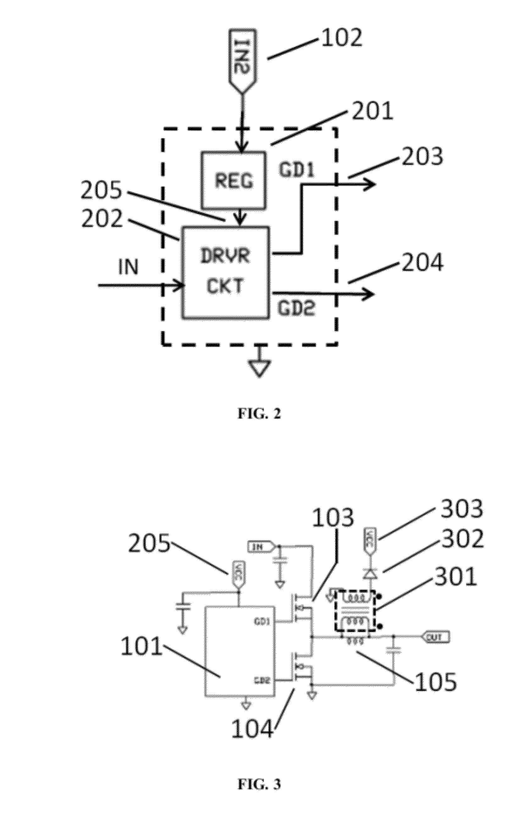
[0029]FIG. 4A and FIG. 4B show two versions of the invention. FIG. 4A shows a simplified diagram of the power stage of a boost converter using a synchronous rectifier, along with the components of this invention. FIG. 4B shows the same simplified diagram of the power stage of the boost converter using a non-synchronous boost diode. FIG. 4B also shows the components of this invention. 101 represents the switching controller or gate driver, or a combination of the two. Transformer (401), rectifier (402) and rectifier output (403) are components of the present invention used with either implementation of the boost converter circuit. 401 through 403 correspond to 301 through 303 respectively as in FIG. 3. Filter capacitors attached between 403 and the ground terminal are not shown for simplicity. 404 is the boost inductor. 407 and 408 are the active power switches. For the synchronous boost converter, the primary winding of 401 is connected across synchronous rectifier (407). Similarly,...


PUM


Abstract

Unique methods are disclosed to construct an efficient bias supply for a main non-isolated DC / DC power conversion system. Additional bias supplies developed by employing an arbitrary number of transformers and / or an arbitrary number of secondary windings can be used to provide bias power to other isolated and non-isolated power conversion systems. By employing a transformer in forward conversion mode the basic circuit of the efficient bias supply is built without using any extra switching controllers and power switches. Furthermore a new architecture for monitoring and selecting the bias power source to ensure smooth start-up and operation during abnormal conditions and / or maintaining optimum and efficient steady state operation of a power conversion system is disclosed.

Description

CROSS REFERENCE TO RELATED APPLICATION[0001]This application claims priority from and incorporates by reference the following US Provisional Application: “Efficient bias power supply for non-isolated DC / DC power conversion applications”, Ser. No. 61 / 520,453 filed on Jun. 10, 2011.BACKGROUND OF THE INVENTION[0002]1. Field of the Invention[0003]The field of the present invention pertains to electrical power conversion. The present invention relates to an efficient bias supply development for non-isolated DC / DC power conversion applications.[0004]2. Description of Related Art[0005]In a typical DC / DC converter such as synchronous buck, synchronous / non-synchronous boost, and other topologies the bias supplies to operate the controller and driver circuit are derived using one or more linear regulators. This causes significant loss in power efficiency. To address this problem, prior art is demonstrated by the following patents:)[0006]a) U.S. Pat. No. 7,202,643 B2 issued to Rais K. Miftakhu...

Claims


Application Information

Patent Timeline
IPC IPC(8): G05F1/618
CPCH02M3/1588Y02B70/1466H02M2001/0003Y02B70/10H02M1/0003
Inventor HUDA, MUZAHID BIN
Owner HUDA MUZAHID BIN
Why Eureka
Try Eureka