
Door closer, particularly for glass doors

Active Publication Date: 2012-12-13
IN & TEC
View PDF12 Cites 13 Cited by
  • Summary
  • Abstract
  • Description
  • Claims
  • Application Information

AI Technical Summary

Benefits of technology

[0008]Object of the present invention is to overcome at least partly the above drawbacks, by providing a door closer having characteristics of high effectiveness, constructional simplicity and low cost.

Problems solved by technology

Such known device has high bulking, since the box-like body has an extremely large size.
Therefore, the installation of such a device requires expensive and difficult break-in works of the floor, which have to be made by qualified operators.
Further, due to the presence of the external arm, the aesthetic appeal of this known door closer is dramatically low.
As a consequence, it can be very unsafe for a user, in particular in case of glass doors.

Method used


Image

  • Door closer, particularly for glass doors
  • Door closer, particularly for glass doors
  • Door closer, particularly for glass doors

Examples


Embodiment Construction

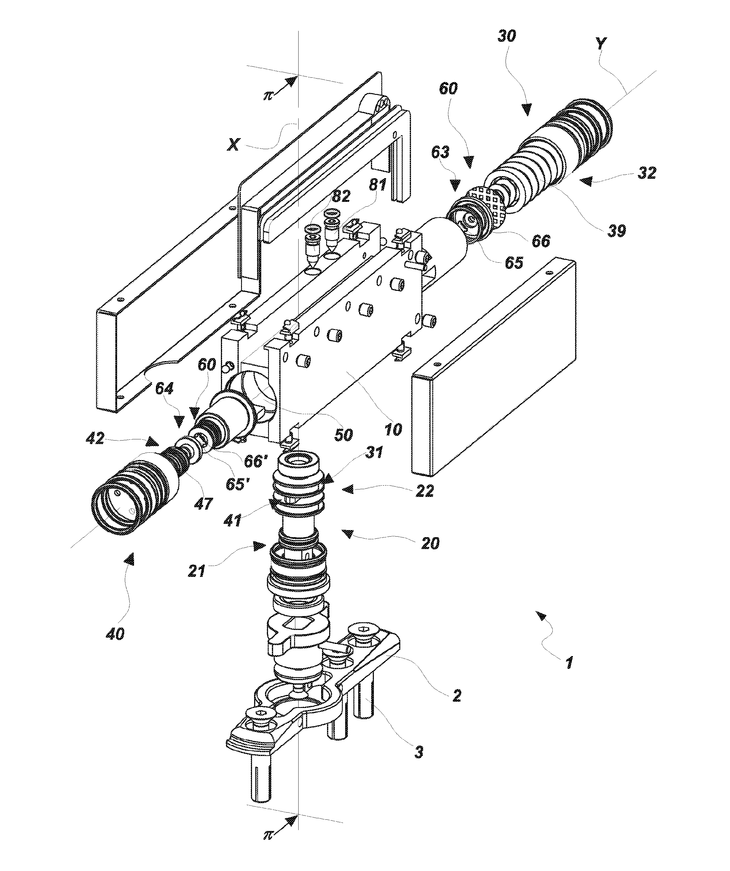
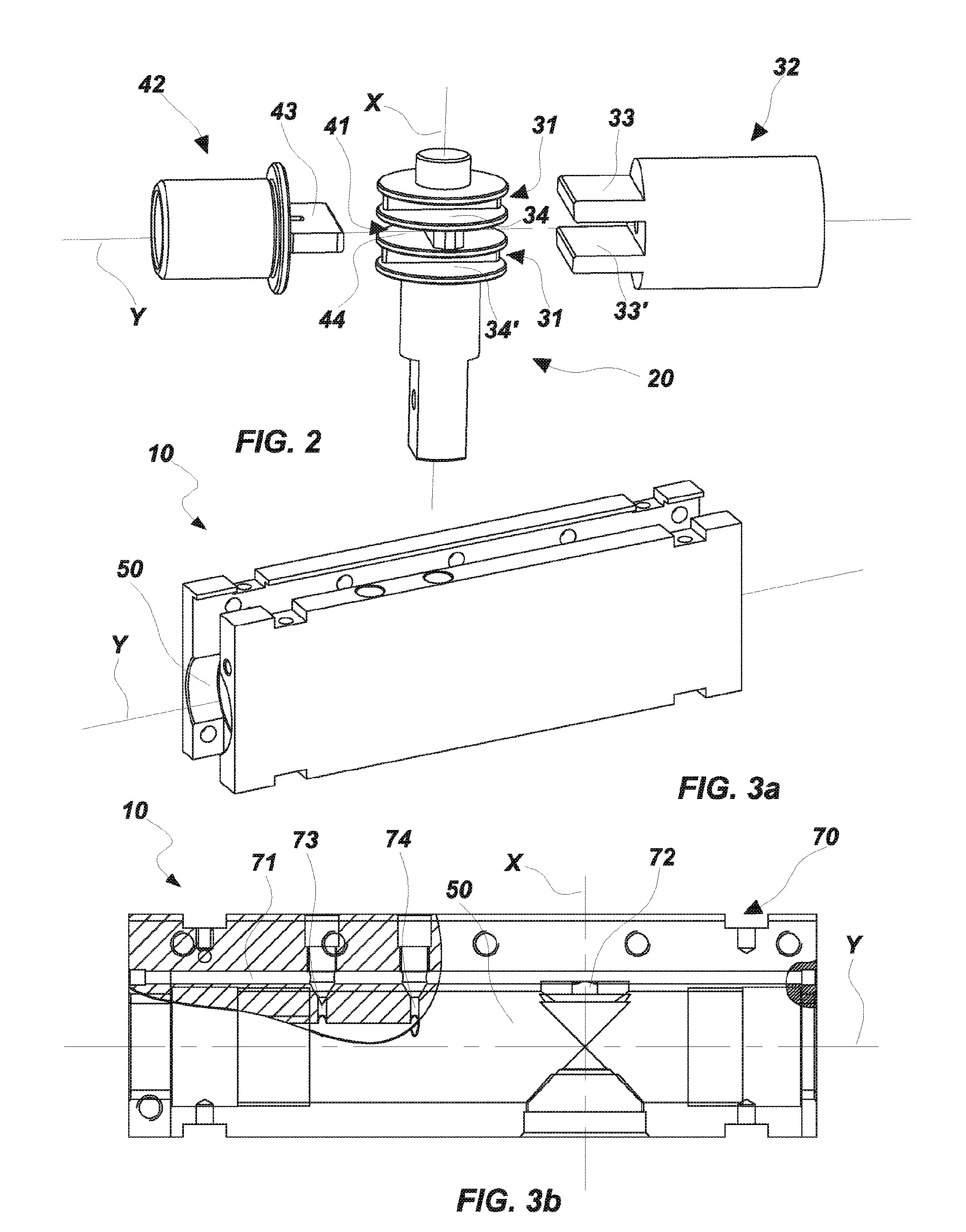
[0059]Referring to the above mentioned figures, the door closer 1 is advantageously applicable to doors, in particular glass doors, which may be supported by a stationary support structure, for example the floor.

[0060]In the figures both the door and the stationary support structure, which are not part of the present invention, have not shown because they are known per se.

[0061]Preferably, as particularly visible in FIG. 1, the door closer 1 may include a plate 2, which may be anchored to the stationary support structure, e.g. the floor, by suitable fastener 3.

[0062]In this manner, it will be possible to install the door closer 1 easily and smoothly, avoiding for instance the expensive and difficult break-in works which are necessary with the known solutions.

[0063]Apparently, the door closer 1 may be equivalently anchored to the support frame of the door.

[0064]The door closer 1 may be used individually, with a simple hinge on the other end of the door, or in a combination of two or ...


PUM


Abstract

A door closer for doors, particularly glass doors, which are supported by a stationary support structure (S) and are movable between an open door position and a closed door position. The door closer comprises a box-like body (10) and a pin (20) reciprocally rotatably coupled to rotate around a first axis (x) between the open door position and the closed door position. Closing means are provided (30) to automatically return the door, as well as a braking means (40) acting thereon to counteract their action. First and second cam elements (31, 41) unitary with the pin (20) and interposed between a first and second plunger elements (32, 42) are provided.

Description

FIELD OF THE INVENTION[0001]The present invention is generally applicable in the technical field of the closing hinges, and particularly relates to a door closer, in particular for glass doors.BACKGROUND OF THE INVENTION[0002]As known, door closer are generally used to close a door which is supported by a stationary structure, e.g. a door frame.[0003]Door closer usually comprise a movable element, fixed to one between the door and the stationary structure, pivoted on a fix element, usually fixed to the other between the door and the stationary structure.[0004]Moreover, closing means acting on the movable element to automatically return the door or the like to the closed position are provided.[0005]From the document EP0407150 a door closer is known, which includes a box-like body and an external arm connectable to the door for the automatic returning thereof to the closed position. Such known device has high bulking, since the box-like body has an extremely large size. Therefore, the...

Claims


Application Information

Patent Timeline
IPC IPC(8): E05F3/04E05F3/00
CPCE05F3/104Y10T16/276E05Y2201/638E05Y2800/22E05F3/226E05Y2600/46E05F3/20E05F3/04E05Y2900/132E05D5/0246E05D7/081Y10T16/2771Y10T16/534Y10T16/552Y10T16/304Y10T16/27Y10T16/593Y10T16/56E05F3/12E05F3/10
Inventor BACCHETTI, LUCIANO
Owner IN & TEC
Learn More