
Cleaning sheet and cleaning tool

a technology applied in the direction of carpet cleaners, cleaning machines, vehicle cleaning, etc., can solve the problems of tensile stress on the end of the cleaning sheet held by the holding member, and the difficulty of avoiding the known cleaning sheet, so as to enhance the use of cleaning sheets and cleaning tools.

Active Publication Date: 2012-12-13
UNI CHARM CORP
View PDF2 Cites 13 Cited by
  • Summary
  • Abstract
  • Description
  • Claims
  • Application Information

AI Technical Summary

Benefits of technology

[0004]In operation of cleaning floor or other objects having a high frictional resistance, with a cleaning sheet attached to a cleaning sheet mounting member of a cleaning tool, a tensile stress acts upon the cleaning sheet in a direction opposite to the direction of movement of the cleaning sheet mounting member. According to the known cleaning sheet, the end portion of the sheet has substantially the same elongation rate across the entire region of the end portion. In this connection, when a tensile stress acts upon the cleaning sheet during cleaning operation and the elongation rate of the end portion is set as relatively low (namely, the rigidity of the end portion is relatively high), the ends of the cleaning sheet easily become detached from the holding members. On the other hand, when a tensile stress acts upon the cleaning sheet during cleaning operation and the elongation rate of the end portion is set as relatively high (namely, the rigidity of the end portion is relatively low), the ends of the cleaning sheet held by the holding member may be easily broken by the tensile stress. In this regard, the known cleaning sheet is in difficulty both to avoid unwilling detachment of the cleaning sheet and to secure rigidity for avoiding easy break of the cleaning sheet held by the holding member.
[0005]Accordingly, it is an object of the invention to enhance a usability of cleaning technique.
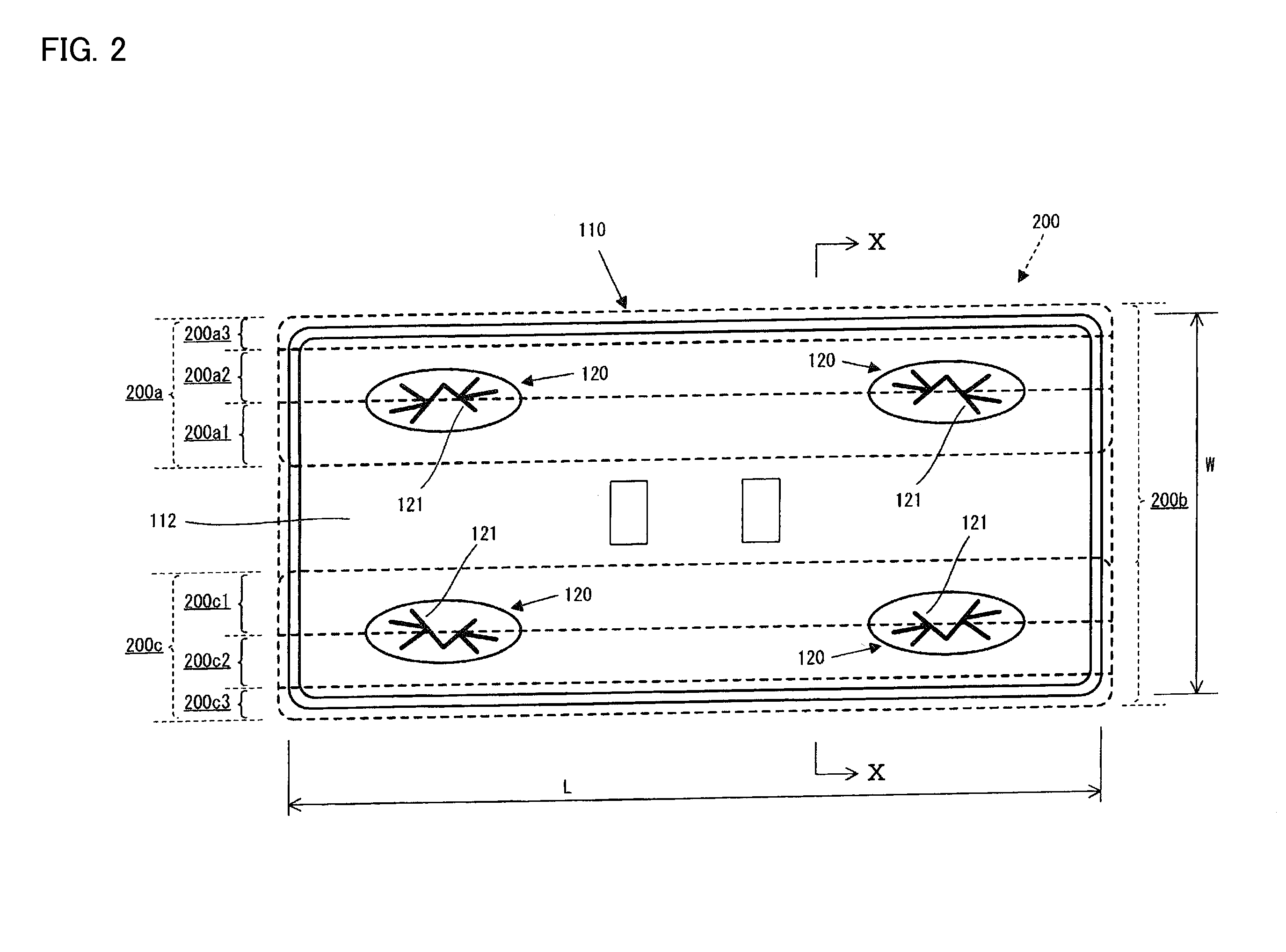
[0010]According to the invention, the second part is disposed between the central portion and the first part in the predetermined direction. A boundary is provided between the first part and the second part. The cleaning sheet is detachably held by the cleaning sheet mounting member at a boundary between the first part and the second part. The cleaning sheet may be held by the cleaning sheet mounting member at least at a part of the boundary. By this construction, when a tensile stress during a cleaning operation acts upon the cleaning sheet attached to the cleaning sheet mounting member, the second part at the boundary having a relatively higher elongation rate (more stretchy) elongates and absorbs the tensile stress, while the first part at the boundary having a relatively lower elongation rate (namely being relatively higher rigidity) securely maintains the engagement between the cleaning sheet and the cleaning sheet mounting member. Thus, at a region where the boundary of the cleaning sheet is held by the cleaning sheet mounting member, the second part with relatively high rate of elongation prevents the cleaning sheet from being unwillingly detached from the cleanings sheet mounting member during the cleaning operation and at the same time, the first part with relatively low rate of elongation prevents the cleaning sheet from being broken due to the tensile stress during the cleaning operation.
[0011]As another aspect of the invention, the elongation rates of the first and second parts are changed according to the number of layers of the sheet elements in the first and second parts. The second part may preferably be formed by a single sheet element or by a plurality of sheet elements stacked in layer and bonded to each other. The first part may preferably be formed by sheet elements stacked in layer and bonded to each other. The number of sheet elements in layer of the first part may be set lager in number than the number of sheet element(s) of the second part such that the second elongation rate is higher than the first elongation rate. Sheet elements in layer may be provided by stacking different sheet elements separately prepared to each other. Otherwise, sheet elements may be provided by folding one sheet element. The stacked sheet elements may preferably be bonded together. With such a construction, predetermined elongation rate can be easily secured. Further, because the first part and the second part is visibly differentiated due to the different number of sheet elements is layer, boundary between the first and second parts can be easily identified by the user for holding by the cleaning sheet holding member.
[0014]According to this aspect, the strength of the central portion side can be enhanced, while the cleaning sheet can be prevented from becoming detached from the cleaning sheet mounting member.

Problems solved by technology

On the other hand, when a tensile stress acts upon the cleaning sheet during cleaning operation and the elongation rate of the end portion is set as relatively high (namely, the rigidity of the end portion is relatively low), the ends of the cleaning sheet held by the holding member may be easily broken by the tensile stress.
In this regard, the known cleaning sheet is in difficulty both to avoid unwilling detachment of the cleaning sheet and to secure rigidity for avoiding easy break of the cleaning sheet held by the holding member.

Method used


Image

  • Cleaning sheet and cleaning tool
  • Cleaning sheet and cleaning tool
  • Cleaning sheet and cleaning tool

Examples


embodiment 1

[0096]Embodiment 1 has the construction shown in FIG. 12. Each of outer layer sheets 220, 230 has a width of 190 mm and has one end in the width direction which is folded so that folded part 220a or 230a is formed. The folded parts 220a, 230a have a length T1 of 20 mm. The outer layer sheets 220, 230 are arranged on both sides of an inner layer sheet 210. In each embodiment, hot embossing is performed on a needed area, which is not particularly specified.

[0097]In embodiment 1, a first part 200a1 (200c1) or the first member X having a lower elongation rate has a two-layer structure having the outer layer sheets 220, 230. A second part 200a2 (200c2) or the second member Y having a higher elongation rate has a single-layer structure having the outer layer sheet 220 (230). Further, the CD direction of the outer layer sheets 220, 230 coincides with the width direction of the sheet (the horizontal direction in FIG. 12).

[0098]According to the embodiment 1, the first member X has the elonga...

embodiment 2

[0099]Embodiment 2 has the construction shown in FIG. 13. Each of outer layer sheets 320, 330 has a width T of 170 mm. The outer layer sheets 320, 330 are arranged on both sides of an inner layer sheet 310, and outer layer sheets 340, 350 having a width K of 20 mm are arranged on the both ends (edges) of the sheet in the width direction.

[0100]In embodiment 2, a first part 300a1 (300c1) or the first member X having a lower elongation rate has a two-layer structure having the outer layer sheets 320 (330), 340 (350). A second part 300a2 (300c2) or the second member Y having a higher elongation rate has a single-layer structure having the outer layer sheet 320 (330). Further, the CD direction of the outer layer sheets 320, 330 coincides with the width direction of the sheet (the horizontal direction in FIG. 13), and the MD direction of the outer layer sheets 340, 350 coincides with the width direction of the sheet.

[0101]According to the embodiment 2, the first member X has the elongatio...

embodiment 3

[0102]Embodiment 3 has the construction shown in FIG. 13. Each of the outer layer sheets 320, 330 has a width T of 170 mm. The outer layer sheets 320, 330 are arranged on the both sides (edges) of the inner layer sheet 310, and 70 g / m2 spunbond nonwoven fabrics (SB) 340, 350 having a width K of 20 mm are arranged on the both ends (edges) of the sheet in the width direction.

[0103]In embodiment 3, the first part 300a1 (300c1) or the first member X having a lower elongation rate has a two-layer structure having the outer layer sheet 320 (330) and the 70 g / m2 spunbond nonwoven fabric 340 (350). A second part 300a2 (300c2) or the second member Y having a higher elongation rate has a single-layer structure having the outer layer sheet 320 (330). Further, the CD direction of the outer layer sheets 320, 330 coincides with the width direction of the sheet (the horizontal direction in FIG. 13).

[0104]According to the embodiment 3, the first member X has the elongation rate of 0.06 mm / N, and th...


PUM


Abstract

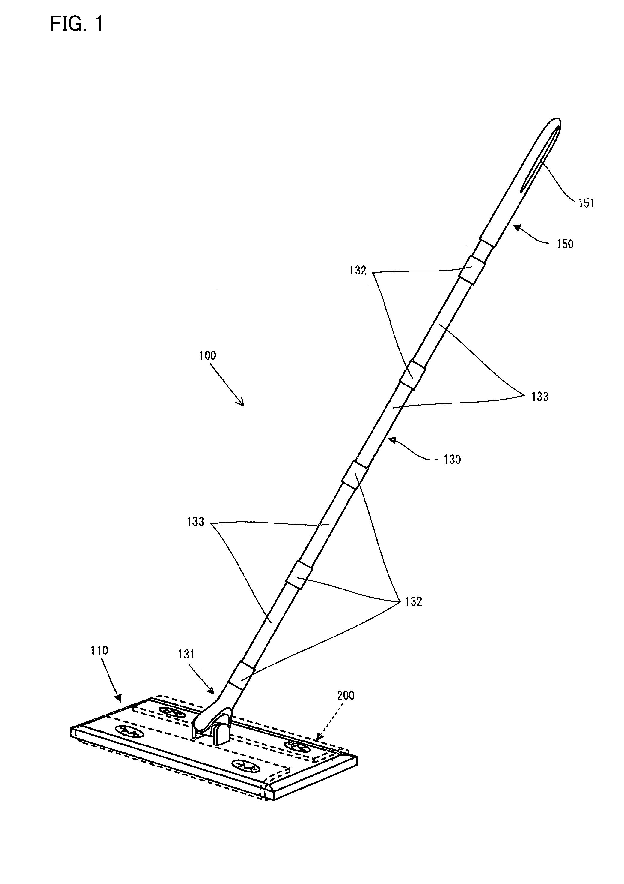
A cleaning sheet and a cleaning tool which have improved usability. The cleaning sheet is attachable to a cleaning-sheet mounting member. The cleaning sheet has a center section made up of a cleaning surface and at least one end section disposed at one or more sides with respect to the center section in a predetermined direction. The end section has a first portion having a first elongation percentage and a second portion having a second elongation percentage which is higher than that of the first portion. The second portion is disposed in said direction between the first portion and the center section and is constructed so as to be supported by the cleaning-sheet mounting member at the boundary between the first and second portions. The cleaning tool is provided with the cleaning sheet.

Description

FIELD OF THE INVENTION[0001]The invention relates to cleaning sheets and cleaning tools, and more particularly to a cleaning sheets and cleaning tools which can be suitably used for wiping an object to be cleaned such as floor.DESCRIPTION OF THE RELATED ART[0002]Japanese non-examined laid-open Patent Publication No. 2007-20615 discloses a cleaning sheet having an inner layer sheet and outer layer sheets integrally formed with the inner layer sheet on both sides of the inner layer sheet. In use, the cleaning sheet can be attached to a cleaning sheet mounting member of a cleaning tool. Central portion of the cleaning sheet is placed on a cleaning side of the cleaning sheet mounting member. Both ends of the cleaning sheet are pushed in between holding members provided in the cleaning sheet mounting member and held between the holding members. According to the known cleaning sheet, low-hydroentangled part is provided with the central portion and high-hydoroentangled part is provided wit...

Claims


Application Information

Patent Timeline
Patent Type & Authority Applications(United States)
IPC IPC(8): A47L13/16A47L13/44
CPCA47L13/256A47L13/20A47L13/16A47L13/44
Inventor HASEGAWA, SATOSHISUDA, TOMOKAZU
Owner UNI CHARM CORP
Learn More