Liquid ejecting apparatus
a technology of ejecting apparatus and liquid, which is applied in the direction of printing, etc., can solve the problems of achieve the effects of reducing the cost of the capping member, increasing the size of the apparatus, and complicated structure of the apparatus
- Summary
- Abstract
- Description
- Claims
- Application Information
AI Technical Summary
Benefits of technology
Problems solved by technology
Method used
Image
Examples
first modified embodiment
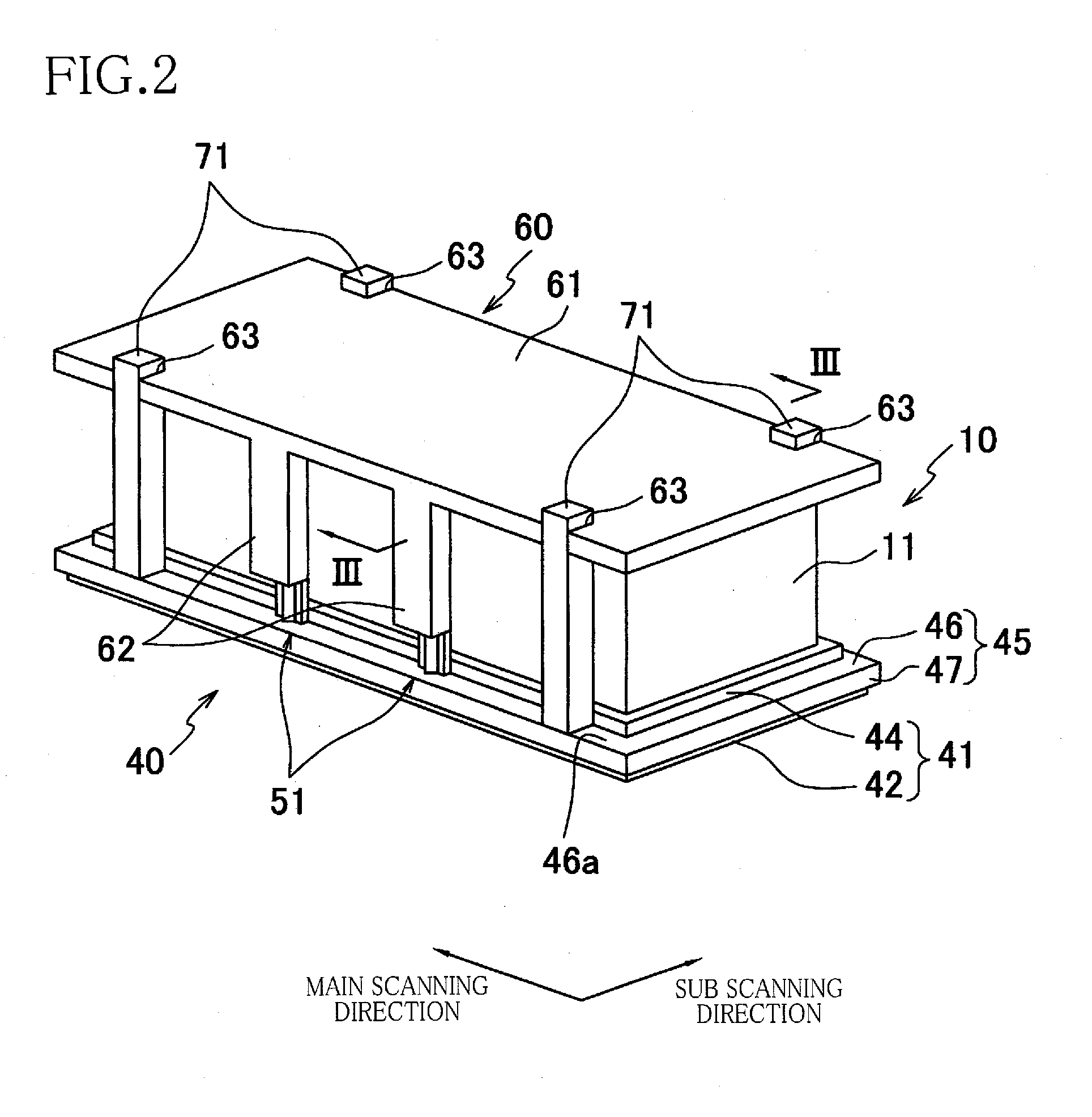
[0070]In the thus constructed capping mechanism 240, the vertical portions 253 of each frame 251 are disposed so as to extend from the holder 45 in the vertically upward direction through the head cover 60. Accordingly, the vertical portions 253 of each frame 251 are in contact with the corresponding guides 62, irrespective of whether the rip 42 is located at the abutting position or the separate position. As in the illustrated embodiment, even where the diaphragm 43 outwardly biases the rip 42 in a direction away from the head 10, the outward deformation of the holder 45 and the rip 42 is restricted by the frames 251 when the rip 42 is located at the abutting position. Therefore, the hermeticity in the hermetically sealed state of the capping mechanism 240 is ensured, thereby suppressing thickening of the ink in the vicinity of the ejection openings 14a. In this first modified embodiment, the structure similar to that in the illustrated embodiment offers advantages similar to those...
second modified embodiment
[0071]Referring next to FIG. 10, there will be explained a capping mechanism 340 according to the invention. In the capping mechanism 340, roller members 351 are attached to the holder 45, in place of the rod members 51 in the capping mechanism 40 in the illustrated embodiment. As shown in FIG. 10, each of the roller members 351 in this second modified embodiment includes two support plates 352 extending from the upper surface 46a of the fixing portion 46 in the vertically outward direction and a roller 353 disposed between the two support plates 352. The roller 353 is rotatably supported by the support plates 352. The roller members 351 are disposed at respective positions of the holder 45 similar to those of the rod members 51 illustrated above. That is, the roller 353 has a shape in which two truncated cones are bonded to each other at bottoms thereof, and an outer circumference of the roller 353 is always in contact with the guide surface 62a of the corresponding guide 62. As sh...
PUM
 Abstract
Description
Claims
Application Information
 - R&D
- Intellectual Property
- Life Sciences
- Materials
- Tech Scout
- Unparalleled Data Quality
- Higher Quality Content
- 60% Fewer Hallucinations
Browse by: Latest US Patents, China's latest patents, Technical Efficacy Thesaurus, Application Domain, Technology Topic, Popular Technical Reports.
© 2025 PatSnap. All rights reserved.Legal|Privacy policy|Modern Slavery Act Transparency Statement|Sitemap|About US| Contact US: help@patsnap.com


