
Quick Release Mechanism For Hanging Projector Mount with Safety Features

a technology of safety features and release mechanisms, which is applied in the direction of machine supports, manufacturing tools, other domestic objects, etc., can solve the problems of disruption of image, disadvantages of simply resting the projector on a flat surface, and disadvantages of hanging semi-permanent mounts

Inactive Publication Date: 2012-12-06
PREMIER MOUNTS
View PDF0 Cites 18 Cited by
  • Summary
  • Abstract
  • Description
  • Claims
  • Application Information

AI Technical Summary

Benefits of technology

[0020]Also disclosed is a method of preventing accidental removal of a two part cylindrical coupling being held together by engagement of projections in one part projecting into recesses in the other part, at least some of the recesses being in communication with channels extending to a distal edge of part on which the channels are located, comprising the steps of: releasing at least some, but not all of the projections from their recesses to allow limited but not complete separation, maintaining the two parts engaged while projections engaged a portion of the channel, twisting the two portions relative to each other to move the projections in the recesses along the channel continuing the rotations along a channel until the projections reach the peripheral edge and thus complete separation of the parts.

Problems solved by technology

However, there were some disadvantages to simply resting the projector on a flat surface.
For instance, the surface could be bumped, causing the projector to vibrate and causing a disruption in the image.
For instance, because the mount is strong, it is relatively insensitive to vibrations caused by bumping a table or desk or other movement in the room.
However, there are still disadvantages to the hanging semi-permanent mounts.
For instance, because many of these mounts emphasize strength and stability, they are not conducive to maintenance of the projector.
The projector may be mounted in an awkward position, such as upside down, and may be well off the floor, so that replacing a bulb may require removing the projector from the mount.
More problematic, once the maintenance has been performed on the projector, it may be difficult to reattach the projector to the mount.
In addition, even if the projector is reattached to the mount, it is likely that the projector has moved slightly from its original position, due to the imprecision of such a mount and the awkwardness of reattaching it.
Finally, once a projector is attached and mounted, its removable can be challenging because, once the projector is released, there is a chance that it will quickly drop and if the installer is not prepared, it could hit the floor.

Method used


Image

  • Quick Release Mechanism For Hanging Projector Mount with Safety Features
  • Quick Release Mechanism For Hanging Projector Mount with Safety Features
  • Quick Release Mechanism For Hanging Projector Mount with Safety Features

Examples


Embodiment Construction

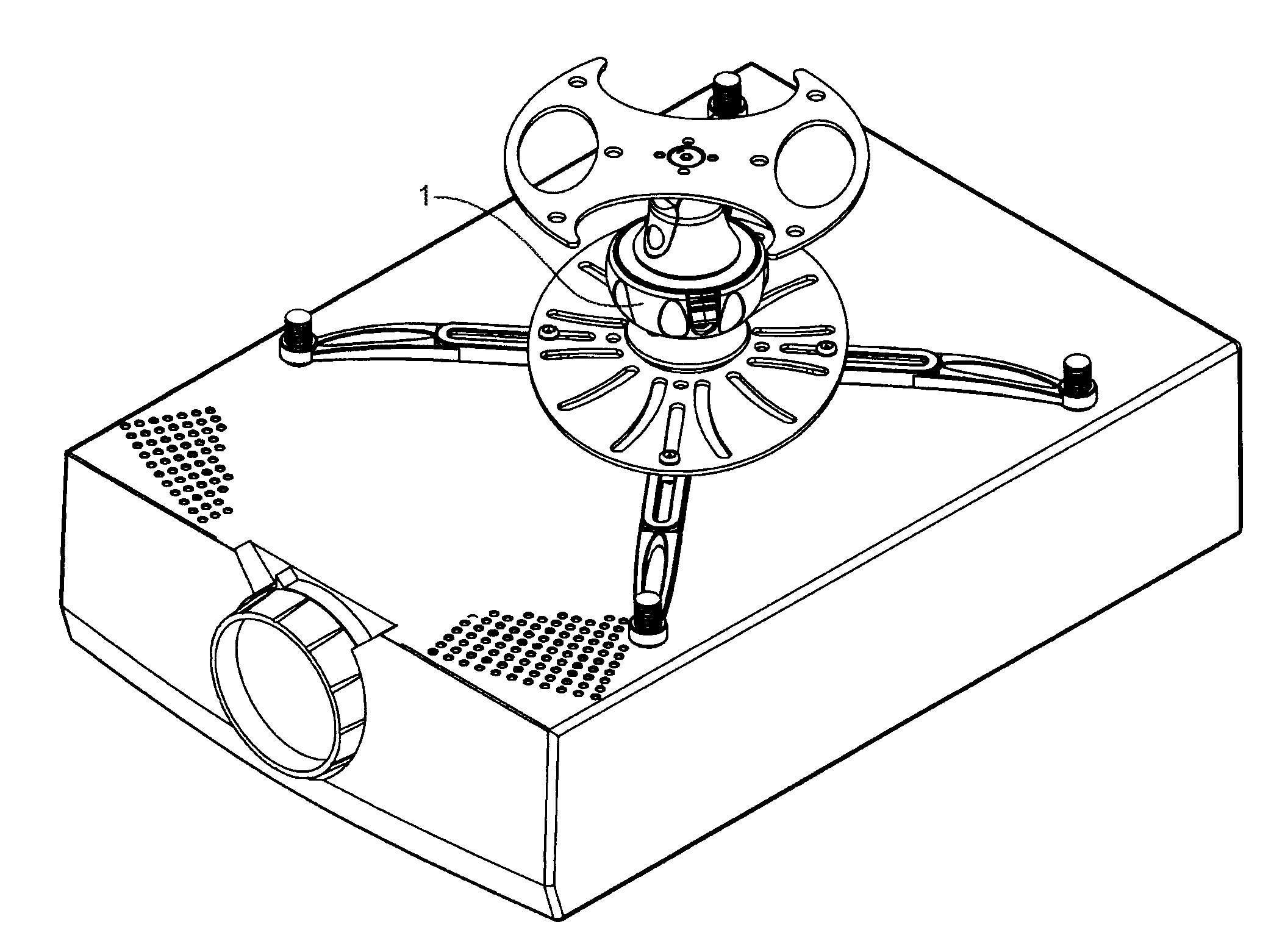
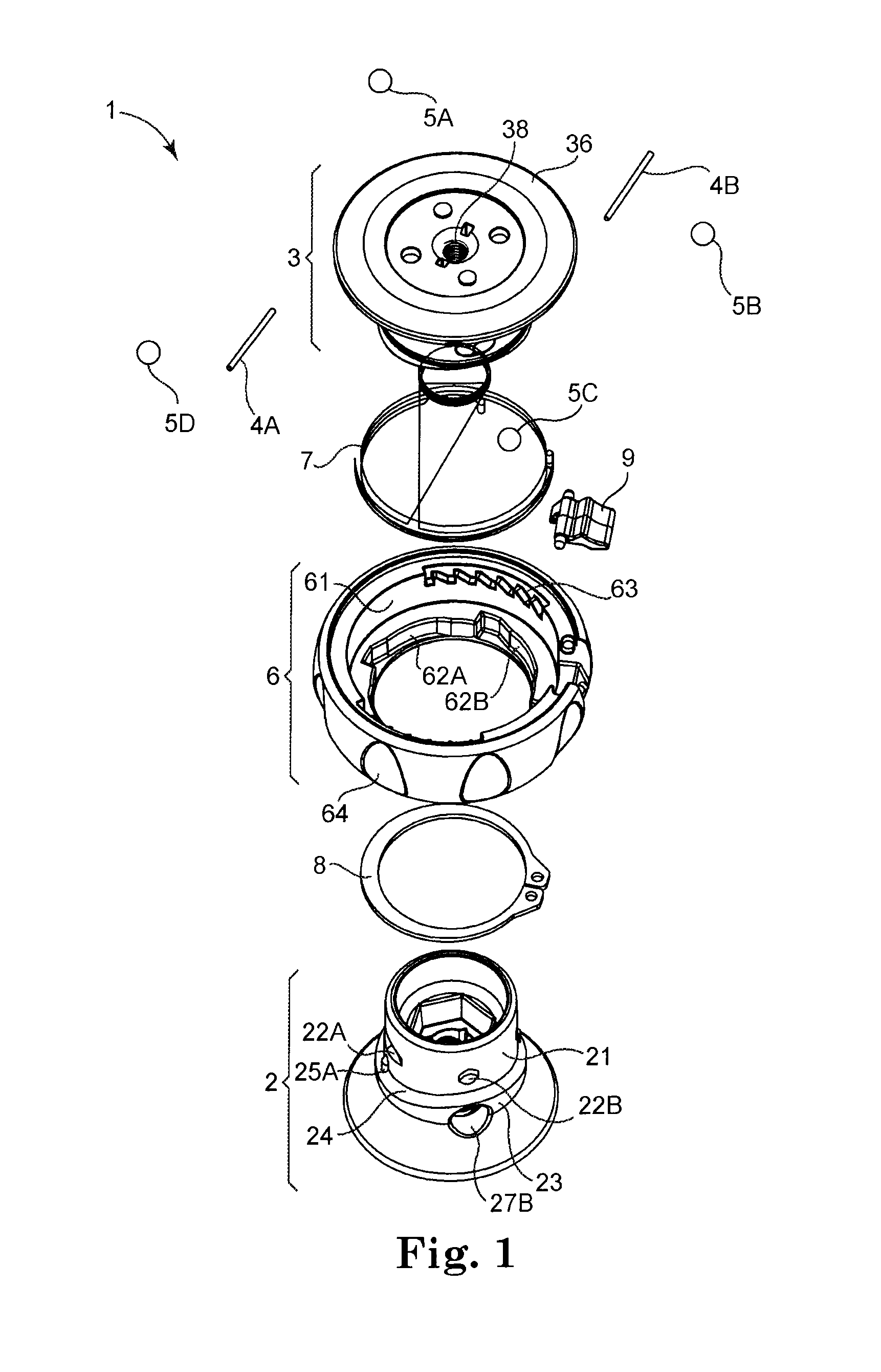
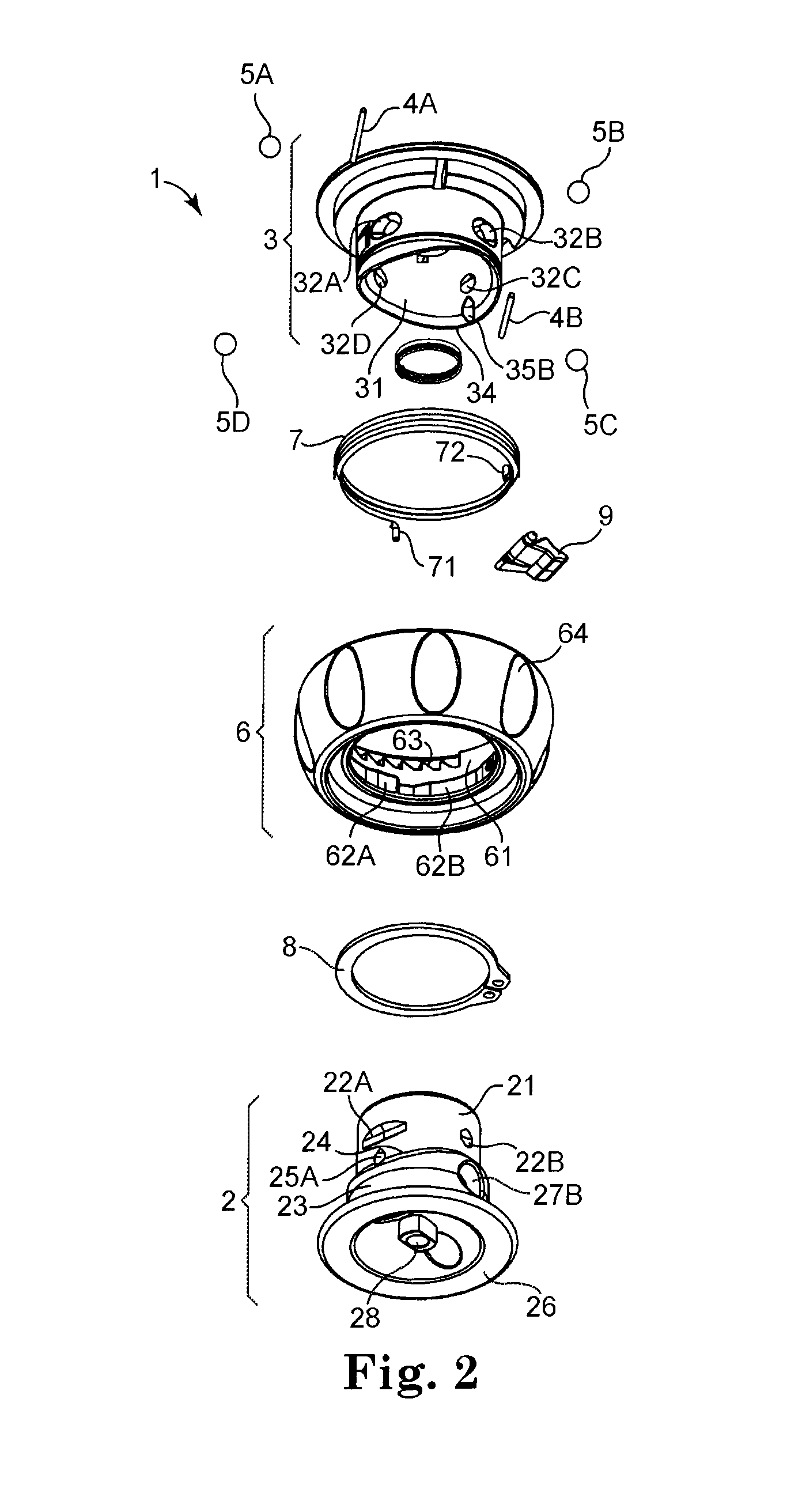
[0043]A quick release mechanism for a hanging projector mount is disclosed, which during use is disposed between the projector 100 and the ceiling. A spindle swivel has a cylindrical portion that fits inside a spindle receiver. The spindle swivel and spindle receiver have a wavy interface between them that ensures at least one preferred azimuthal (circumferential) orientation between them when they are forced together. A twist lock collar is pivotally attached to the spindle receiver, and may be rotated by a user around a central axis, against the action of a torsion spring, from a locked position to an unlocked position. In the locked position, various ramps inside the twist lock collar force respective steel balls radially inward through respective holes in the spindle receiver to engage respective notches in the cylindrical portion of the spindle swivel. In the unlocked position, the ramps decrease the radial inward force on the steel balls, disengaging them from the notches, and...


PUM

PropertyMeasurementUnit
outer diameteraaaaaaaaaa
lengthaaaaaaaaaa
rotationaaaaaaaaaa

Abstract

A safety feature for a spindle swivel has a cylindrical portion that fits inside a spindle receiver. The spindle swivel and spindle receiver have a wavy interface between them that ensures at least one preferred azimuthal orientation between them when they are forced together. A twist lock collar is pivotally attached to the spindle receiver, and may be rotated by a user around a central axis, against the action of a torsion spring, from a locked position to an unlocked position. In the locked position, various ramps inside the twist lock collar force respective steel balls radially inward through respective holes in the spindle receiver to engage respective notches in the cylindrical portion of the spindle swivel. In the unlocked position, the ramps decrease the radial inward force on the steel balls, disengaging them from the notches, and the spindle swivel may be separated from the spindle receiver by the user. The safety feature unlocks only some of the balls from their recesses. The remaining balls are forced thru a channel which prevents direct removal of the spindle without rotation thereof, preventing accidental unexpected disengagement.

Description

BACKGROUND[0001]1. Technical Field[0002]The present invention is directed to a quick release mechanism for a hanging a device, most likely a projector.[0003]2. Description of the Related Art[0004]There is a long history of using projectors in conference rooms and classrooms. As far back as the 1950s, filmstrip and slide projectors were used to project images on a screen or a wall. Back then, the projectors rested on a flat surface, such as a table, counter and shelf. For some elaborate setups, the projector rested on a dedicated cart that could be wheeled around as needed.[0005]Back then, it was relatively easy to access the projector, to replace a bulb or perform some other maintenance. However, there were some disadvantages to simply resting the projector on a flat surface. For instance, the surface could be bumped, causing the projector to vibrate and causing a disruption in the image. In addition, because the projector was typically just above the level of the audience members' ...

Claims


Application Information

Patent Timeline
Patent Type & Authority Applications(United States)
IPC IPC(8): F16M13/00B23P11/00
CPCF16M11/041Y10T29/49815F16M13/027
Inventor BOUISSIERE, MICHAEL F.
Owner PREMIER MOUNTS
Learn More