
Apparatus And Method for Proximal-to-Distal Endoluminal Stent Deployment

a technology applicator, which is applied in the field of applicator and method of distal to distal endoluminal stent deployment, can solve the problem of distal to distal stent installation

Active Publication Date: 2012-11-22
CASELNOVA RALPH F
View PDF13 Cites 28 Cited by
  • Summary
  • Abstract
  • Description
  • Claims
  • Application Information

AI Technical Summary

Benefits of technology

[0007]A prosthetic delivery device is disclosed herein, being for use in introducing a stent within a lumen through a reverse deployment procedure, with deployment beginning at a proximal end location and finishing at a distal end location. The prosthetic delivery device may comprise an inner tube assembly, a rotation tube assembly, and an outer tube assembly. The rotation tube assembly may be threadably engaged with the inner tube assembly. The outer tube assembly may be received over the rotation tube and be fixed relative to the inner tube. The rotation tube may comprise a sheath that concent

Problems solved by technology

A major drawback of all of these devices is that they install the stent in the distal-to-proximal direction.

Method used


Image

  • Apparatus And Method for Proximal-to-Distal Endoluminal Stent Deployment
  • Apparatus And Method for Proximal-to-Distal Endoluminal Stent Deployment
  • Apparatus And Method for Proximal-to-Distal Endoluminal Stent Deployment

Examples


Embodiment Construction

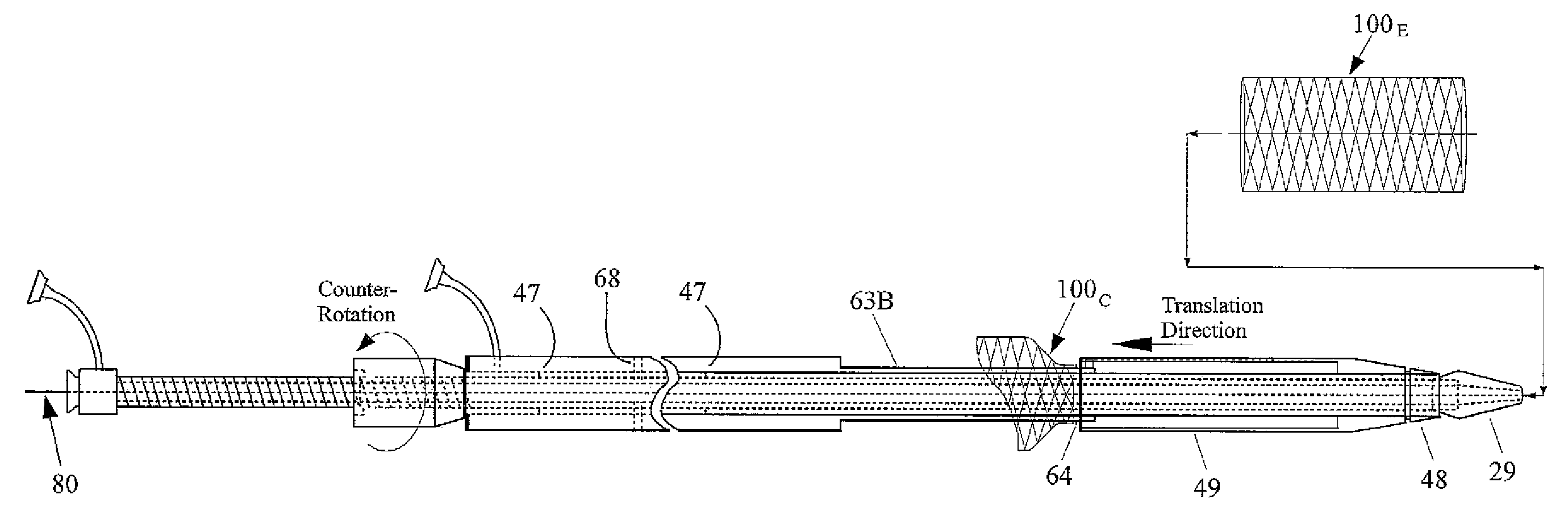
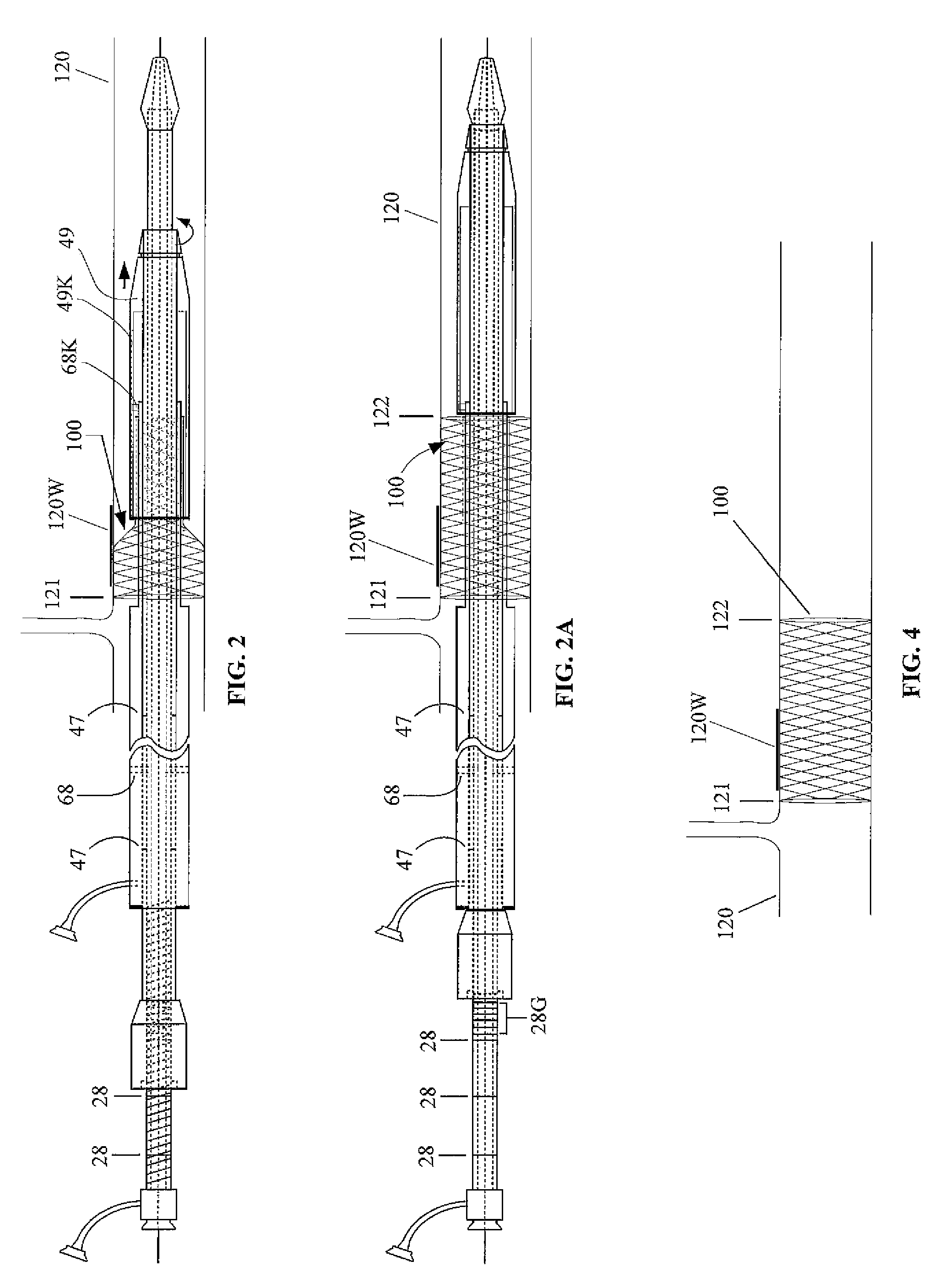
[0018]FIG. 1 shows a first embodiment of a prosthetic delivery device 10, being particularly adapted for introducing a stent within a lumen of a vessel, through a deployment procedure that is reversed with respect to conventional deployment, where deployment herein begins with the stent self-expanding at a desired proximal end location, and finishing at a distal end location. The main component parts of the prosthetic delivery device 10 comprise an inner guide tube assembly 20, a rotation tube assembly 40, and an outer tube assembly 60, each of which is shown individually within FIGS. 5, 6, and 7 respectfully.

[0019]The inner guide tube assembly 20 (FIG. 5) may have a first end 21 and a second end 22. The inner tube assembly 20 may comprise a flexible hollow tube 23 being of sufficient length to reach the sites that are typically the area targeted to receive a stent. A region 24 of the exterior of the inner tube 20, being proximate to the first end 21, may have external threading 25 ...


PUM


Abstract

A prosthetic delivery device is adapted for introducing a stent within a patient's vasculature through a reverse deployment procedure, beginning at a proximal location and finishing at a distal location. The device comprises: a guide tube, a rotation tube, and an outer tube. The guide tube threadably receives the rotation tube thereon. The rotation tube comprises a sheath rotatably secured at one end to overhang over a portion of the outer tube, which is received over a portion of the rotation tube, and which is fixedly secured to the guide tube. Rotating the rotation tube causes its translation relative to the outer tube. A stent crimped to be disposed beneath the sheath is forced to deploy proximally by relative movement of an annular deployment ring on the outer tube. A key on the outer tube is received within a key way of the sheath to prevent its rotation.

Description

CROSS REFERENCES TO RELATED APPLICATIONS[0001]This application claims priority on U.S. Provisional Application Ser. No. 61 / 519,238, filed on May 18, 2011, the disclosures of which are incorporated herein by reference.FIELD OF THE INVENTION[0002]The present invention relates to improvements in methods and apparatus used in the deployment of stents, and more particularly to apparatus which is capable of installing such devices with high fidelity in proximal relation to specific intraluminal locations.BACKGROUND OF THE INVENTION[0003]The blood vessels and arteries, lymphatic vessels, the ureters of the urinary system, and other ducts within the human body, are subject to degradation. Weaknesses in the walls of these ducts may result from a number of different reasons, such as a ureter being compromised by a kidney stone, or a blood vessel weakening due to atherosclerosis and aging. A minimally invasive surgical treatment for weakened, aneurysmal, or ruptured vessels may comprise the in...

Claims


Application Information

Patent Timeline
IPC IPC(8): A61F2/84
CPCA61F2/962
Inventor CASELNOVA, RALPH F.
Owner CASELNOVA RALPH F
Learn More