
Tension Rod

Active Publication Date: 2012-11-15
INTERDESIGN
View PDF3 Cites 32 Cited by
  • Summary
  • Abstract
  • Description
  • Claims
  • Application Information

AI Technical Summary

Benefits of technology

[0006]An object of the present invention is to provide an improved tension rod which can be expanded in a quick and easy way against opposing surfaces to hold the tension rod in place.

Problems solved by technology

However, such of the rods often require a great number of rotations to get the desired length, and often cannot maintain a tight enough fit over time to maintain the rod in place, essentially under downwardly transverse loads.
In some instances a biasing spring is combined with combinations of threaded rods, such as in U.S. Pat. No. 670,585 (Fowler), U.S. Pat. No. 856,316 (Thurston), U.S. Pat. No. 1,548,053 (Mead), U.S. Pat. No. 2,199,851 (Culver), CH 625601 (Baumann) and JP 2055100 (Wada), but these have not been found effective.
This can be difficult to do where there is no easy access between the walls and may not produce a tight fit.
None of the foregoing patent disclosures discloses a compression coil spring in a tension rod which maintains nearly constant tension before, during and after the tension rod is installed.

Method used


Image

  • Tension Rod
  • Tension Rod
  • Tension Rod

Examples


Embodiment Construction

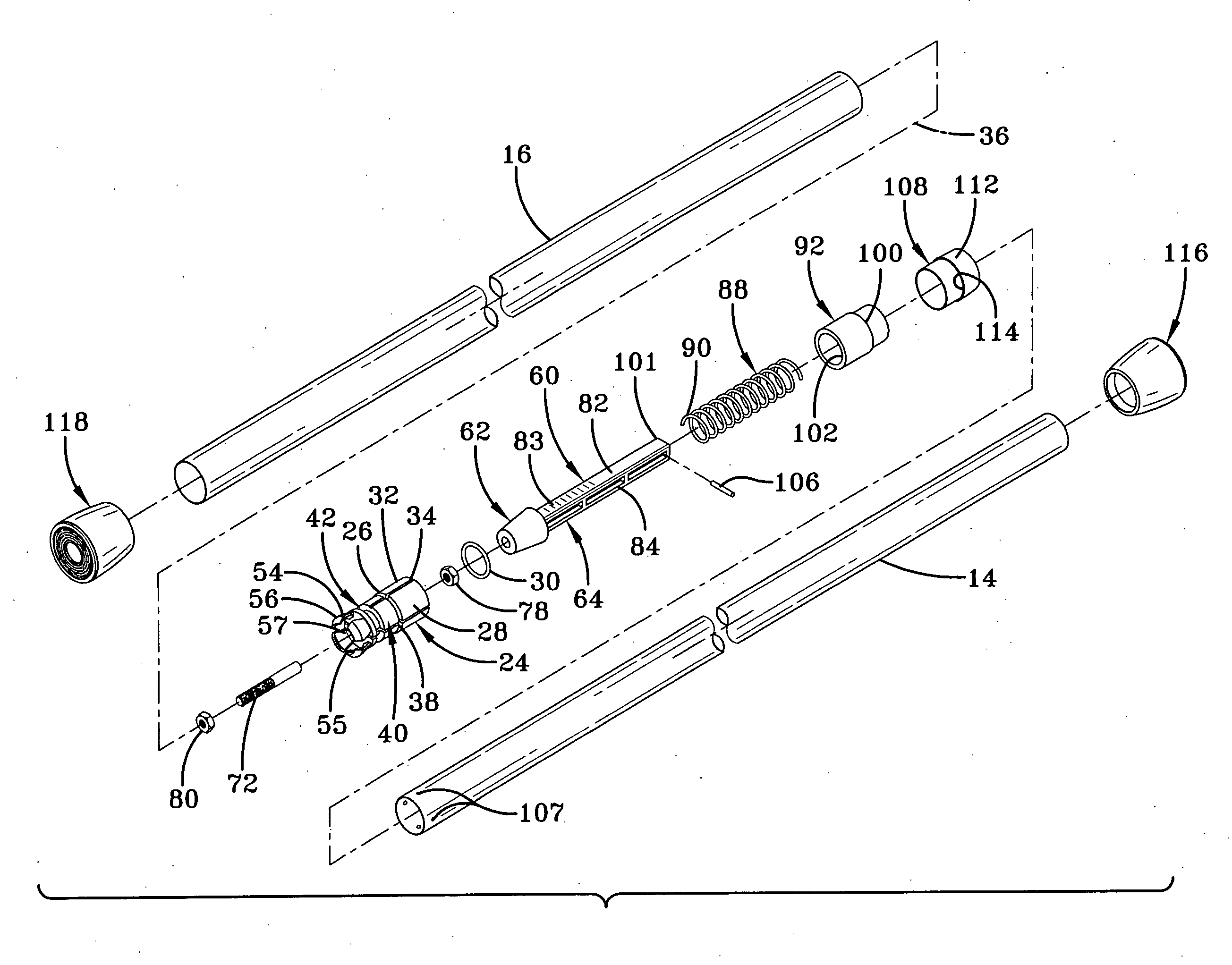
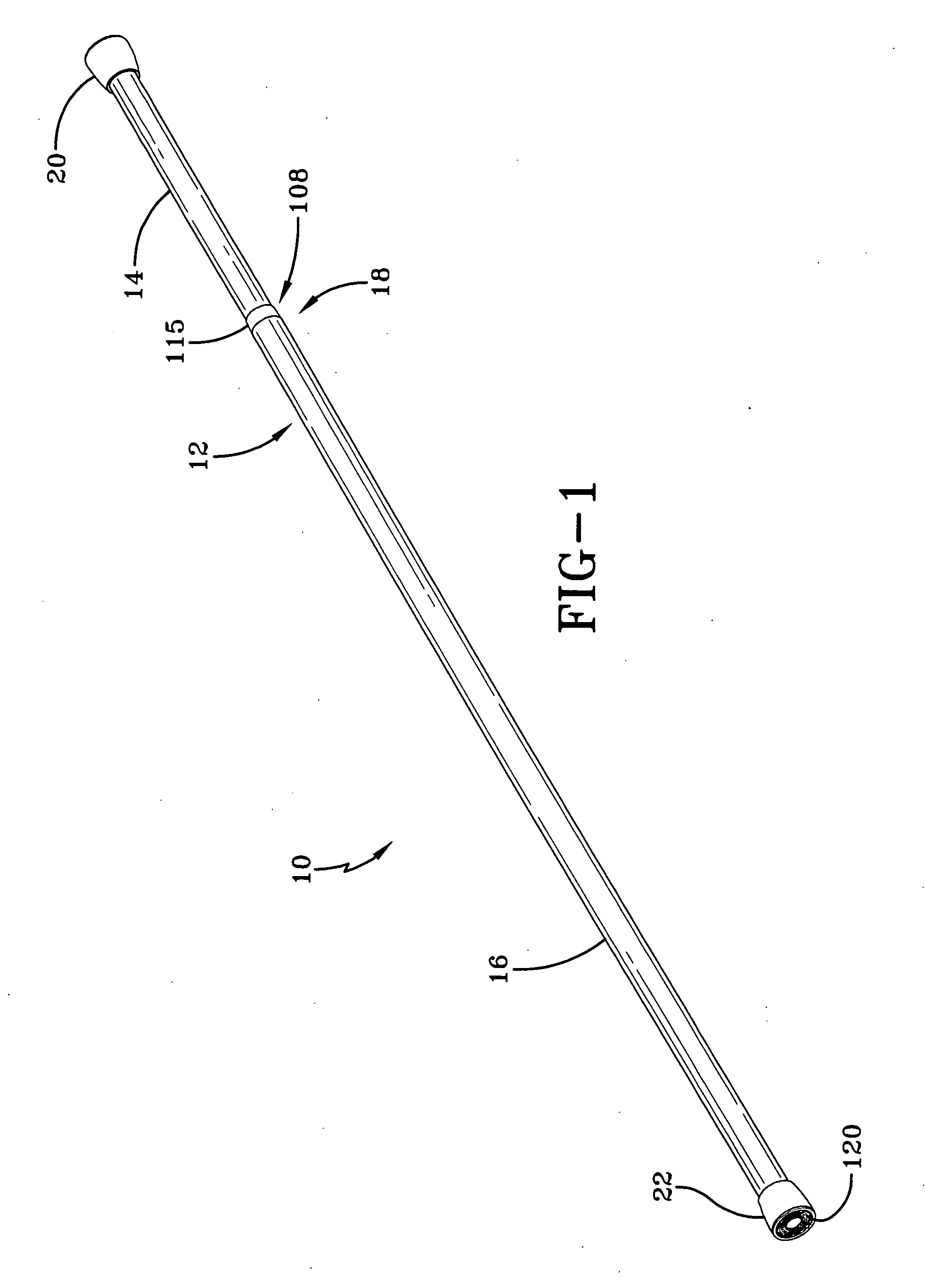
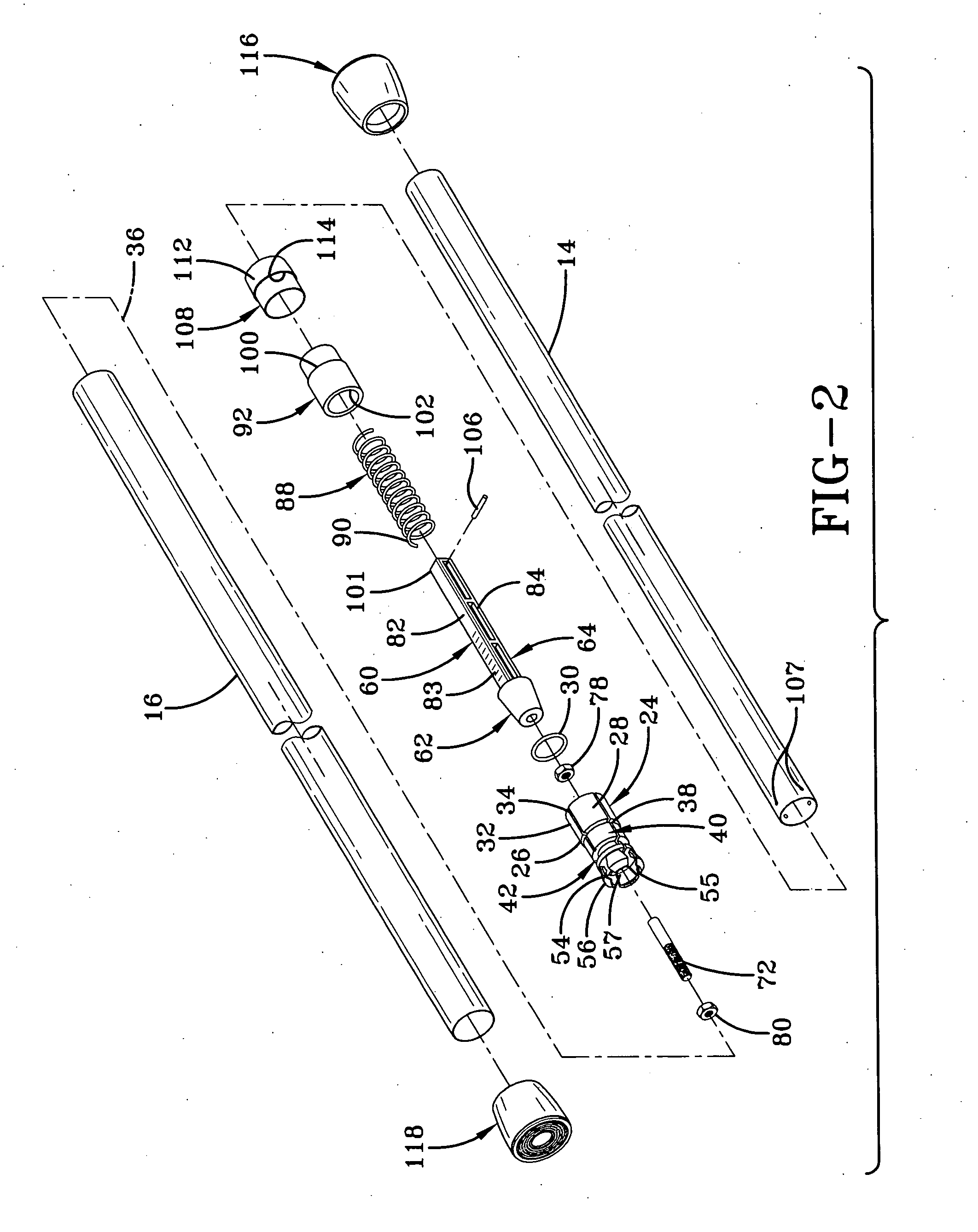
[0038]The invention relates to tension rods, and comprises structure for locating a biasing device in the outer tube of a telescoping arrangement of an inner tube slidable in an outer tube, compressing the biasing device and fixing a biasing support structure at a predetermined location in the outer tube to enable the biasing device to expand the tubes to mount the tension rod between support surfaces. In its basic form, the invention includes a compressible biasing device which is preferably a compressible coil spring. The invention further has a biasing device support structure for initially being locatable at a predetermined position in the outer tube, assisting in the compression of the biasing device, and having members for fixing the biasing device support structure in the outer tube, after which the biasing device releasably mounts the tension rod in place. In its preferred form, the biasing device support structure is an expansion joint structure having resilient leaves for ...


PUM


Abstract

A tension rod comprising in its preferred form an outer tube and an inner tube in a telescoping arrangement. The outer tube has an expansion joint structure which can engage the inner surface of the outer tube to hold it in place. A spring stem-wedge-rod structure has a wedge portion with a threaded rod extending therefrom for being threaded through a nut held in the expansion rod structure. The spring stem-wedge-rod structure has a stem extending through a coil spring, and a spring retainer is fixed both to the stem and to the inner tube. Twisting of the inner tube causes the wedge portion to effect the expansion joint structure to be fixed in the outer tube, and the coil spring provides the tension to mount the tension rod between a pair of opposing wall surfaces.

Description

BACKGROUND OF THE INVENTION[0001]1. Field of the Invention[0002]This invention relates to tension rods, and in particular to tension rods for expanding against opposite walls or other support surfaces for holding curtains, hangers or other articles in place on the tension rod.[0003]2. Description of the Prior Art[0004]Tension rods incorporating telescoping tubes for being installed between walls having different distances between them are well known in the art. Typical tension rods are known for hanging shower curtains. A number of such rods are known having long coil compression springs which are compressed as the telescoping tubes are pressed together and then released so the spring can expand and press the tubes against the walls. However, those rods show the least amount of tension force when the spring is in its expanded state when advantageously it should have its greatest strength, and show the highest tension force when the spring is in its compressed state. In some cases, t...

Claims


Application Information

Patent Timeline
IPC IPC(8): F16M13/00
CPCA47H1/022Y10T403/32501Y10T403/5726
Inventor CARNEY, JOHN R.
Owner INTERDESIGN
Learn More