
Lightning protection system for a wind turbine and wind turbine with a lightning protection system

a protection system and wind turbine technology, applied in the field of wind turbines, can solve the problems of destroying permanent magnets, generator windings, generator windings, etc., and lightning protection systems like these are not applicable to direct drive wind turbines

Active Publication Date: 2012-10-25
SIEMENS GAMESA RENEWABLE ENERGY AS
View PDF9 Cites 19 Cited by
  • Summary
  • Abstract
  • Description
  • Claims
  • Application Information

AI Technical Summary

Benefits of technology

[0072]The invention that has been described with reference to the embodiments offers the following advantages:
[0073]It is easy to implement in actual wind turbine designs.

Problems solved by technology

Lightning strikes are a major reason for wind turbine failures.
The current flowing through the wind turbine must not reach any electrical components like the generator or converter or other critical components like the main bearings or the gearbox as they would be damaged by the large energy of the lightning strike.
The combination of a high voltage and a large electrical current from the lightning strike could damage these components.
The large current of up to 200 kA could destroy the permanent magnets, the generator windings and could introduce metallic particles between rotor and stator.
Therefore, lightning protection systems like these are not applicable for direct drive wind turbines.
For a direct drive wind turbine having a generator with an outer rotating rotor it is even more difficult to find a way to conduct the electrical current from a lightning strike onto the blades to the blades without damaging the generator or other components of the wind turbine.

Method used


Image

  • Lightning protection system for a wind turbine and wind turbine with a lightning protection system
  • Lightning protection system for a wind turbine and wind turbine with a lightning protection system
  • Lightning protection system for a wind turbine and wind turbine with a lightning protection system

Examples


Embodiment Construction

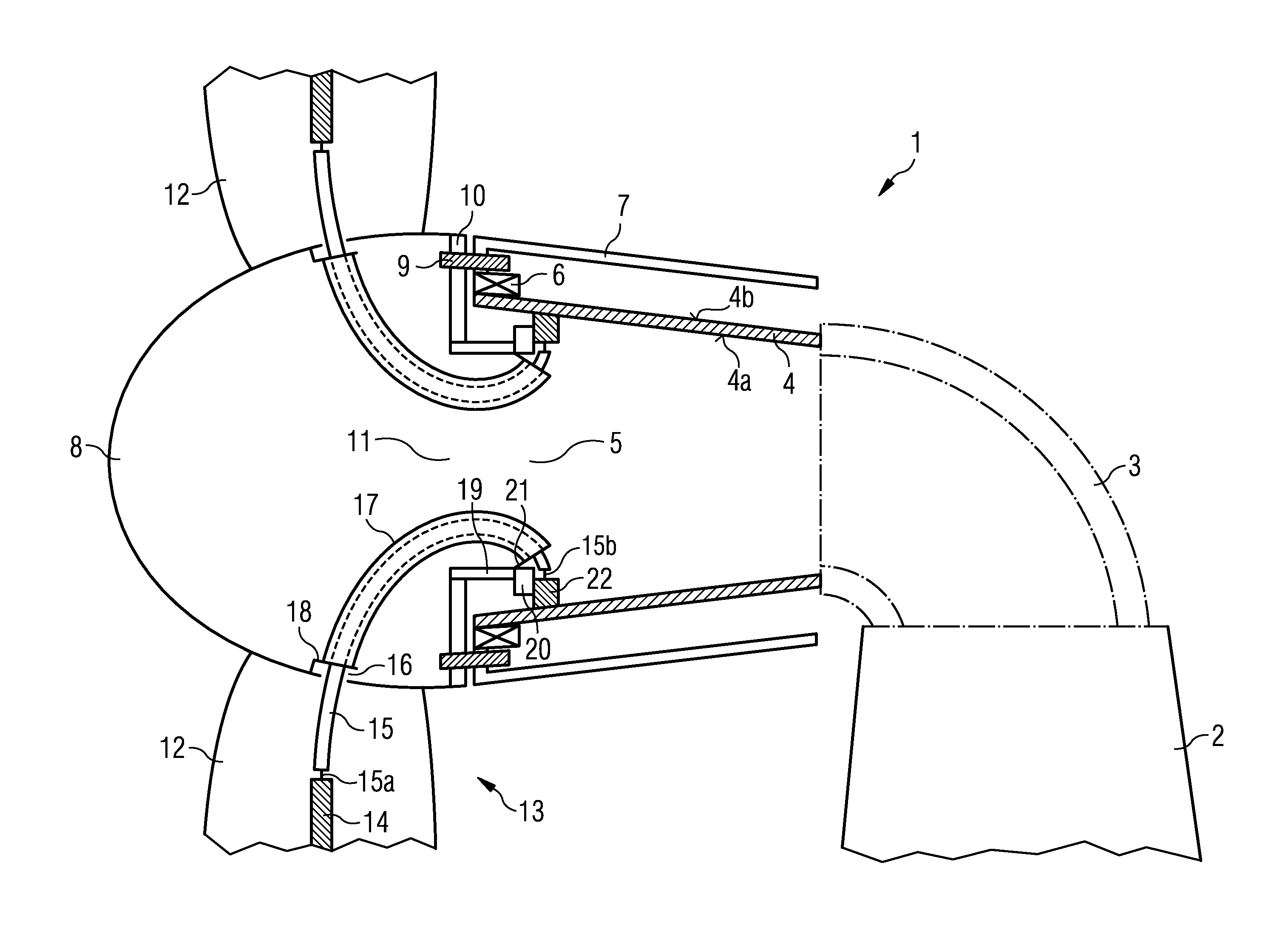
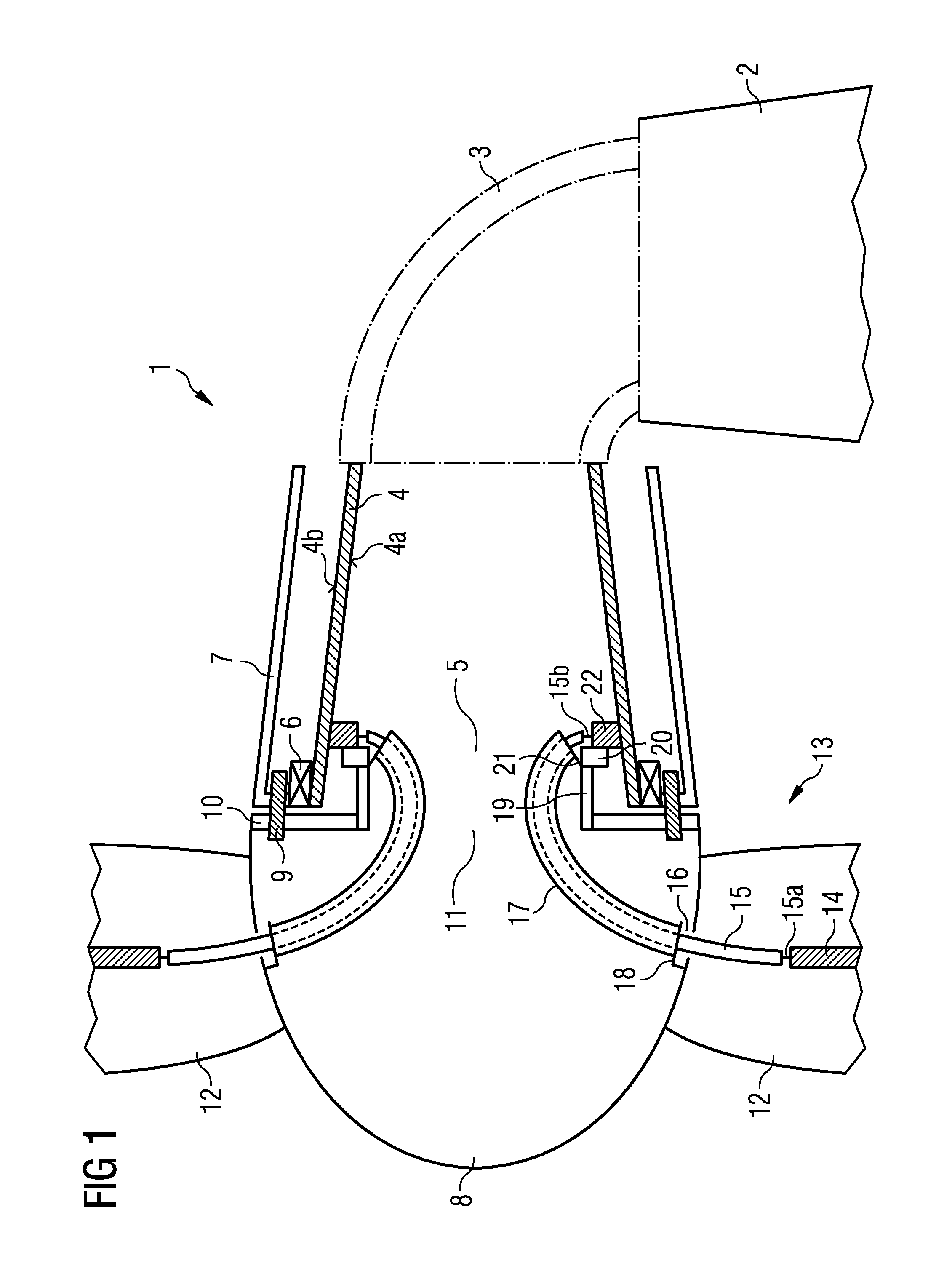
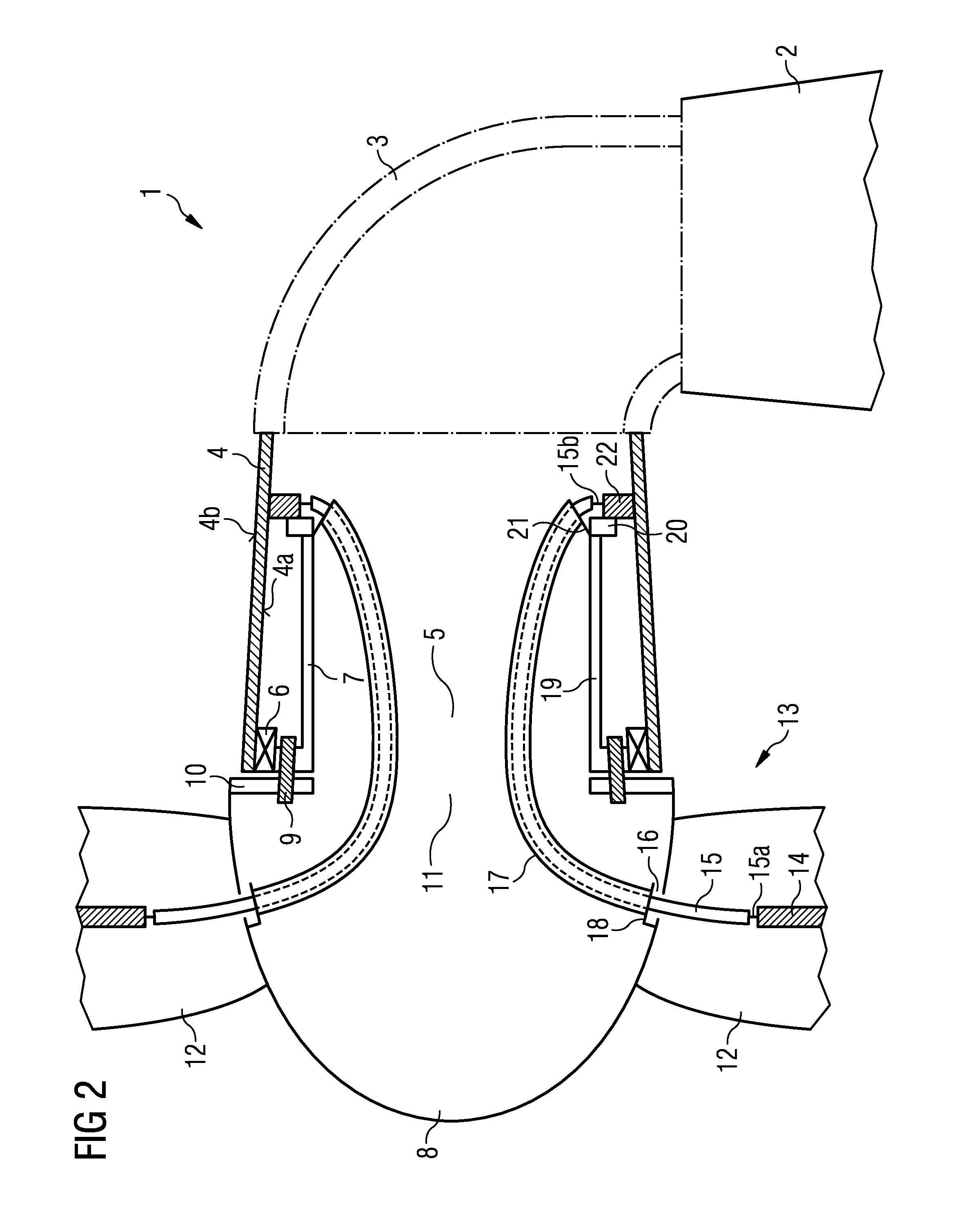
[0028]In the following detailed description, reference is made to the accompanying drawings which form a part hereof and in which are shown by way of illustration specific embodiments in which the invention may be practised. In this regard, directional terminology, such as “top” or “bottom” etc. is used with reference to the orientation of the Figure(s) being described. Because components of embodiments can be positioned in a number of different orientations, the directional terminology is used for purposes of illustration and is in no way limiting. It is to be understood that other embodiments may be utilized and structural or logical changes may be made without departing from the scope of the present invention. The following detailed description, therefore, is not to be taken in a limiting sense, and the scope of the present invention is defined by the appended claims.

[0029]The following exemplary embodiments of the invention describe lightning protection system of a wind turbine ...


PUM


Abstract

A lightning protection system is provided for a wind turbine. The wind turbine has an electrically grounded structure part, a main shaft electrically and mechanically connected to the grounded structure part, a blade hub rotationally connected via a main bearing to the main shaft and blades connected to the blade hub. The lightning protection system includes a down-conductor attachable inside one of the blades and a high voltage conductor for guiding lightning current, wherein a first end of the high voltage conductor is in electrical communication with the down-conductor. The lightning protection system also includes a high voltage contact attachable inside the main shaft, wherein a second end of the high voltage conductor is in electrical communication with the high voltage contact. Lightning current is guided from the down-conductor via the high voltage conductor to the high voltage contact.

Description

CROSS REFERENCE TO RELATED APPLICATIONS[0001]This application is the US National Stage of International Application No. PCT / EP2010 / 052681, filed Mar. 3, 2010 and claims the benefit thereof. The International Application claims the benefits of European application No. 09015262.0 EP filed Dec. 9, 2009. All of the applications are incorporated by reference herein in their entirety.FIELD OF INVENTION[0002]The present invention relates in general to wind turbines. In particular, the present invention is directed to a lightning protection system for a wind turbine and a wind turbine with a lightning protection system.BACKGROUND OF INVENTION[0003]Lightning strikes are a major reason for wind turbine failures. When a lightning strikes a wind turbine often one or more blades of the wind turbine are hit. From there the current of the lightning strike is usually conducted by conducting means like a down-conductor to one or more wind turbine components like the hub, nacelle or the tower and the...

Claims


Application Information

Patent Timeline
Patent Type & Authority Applications(United States)
IPC IPC(8): F03D11/00
CPCY02E10/722F03D11/0033F03D80/30Y02E10/72H02G13/00
Inventor LEWKE, BASTIAN
Owner SIEMENS GAMESA RENEWABLE ENERGY AS
Learn More