
Workpiece feeder and adjustment-and-separation apparatus

Active Publication Date: 2012-10-18
NHK SPRING CO LTD
View PDF5 Cites 14 Cited by
  • Summary
  • Abstract
  • Description
  • Claims
  • Application Information

AI Technical Summary

Benefits of technology

[0011]An object of the present invention is to provide a workpiece feeder capable of preventing workpieces from hitting or rubbing one another and an adjustment-and-separation apparatus used with the workpiece feeder.

Problems solved by technology

When many parts are charged into the vibration bowl and are continuously vibrated, the parts hit and rub one another or the bowl, to create dust such as particles and contaminants.
These related arts, however, are unable to prevent parts in a vibration bowl from hitting and rubbing one another or the bowl.

Method used


Image

  • Workpiece feeder and adjustment-and-separation apparatus
  • Workpiece feeder and adjustment-and-separation apparatus
  • Workpiece feeder and adjustment-and-separation apparatus

Examples


Embodiment Construction

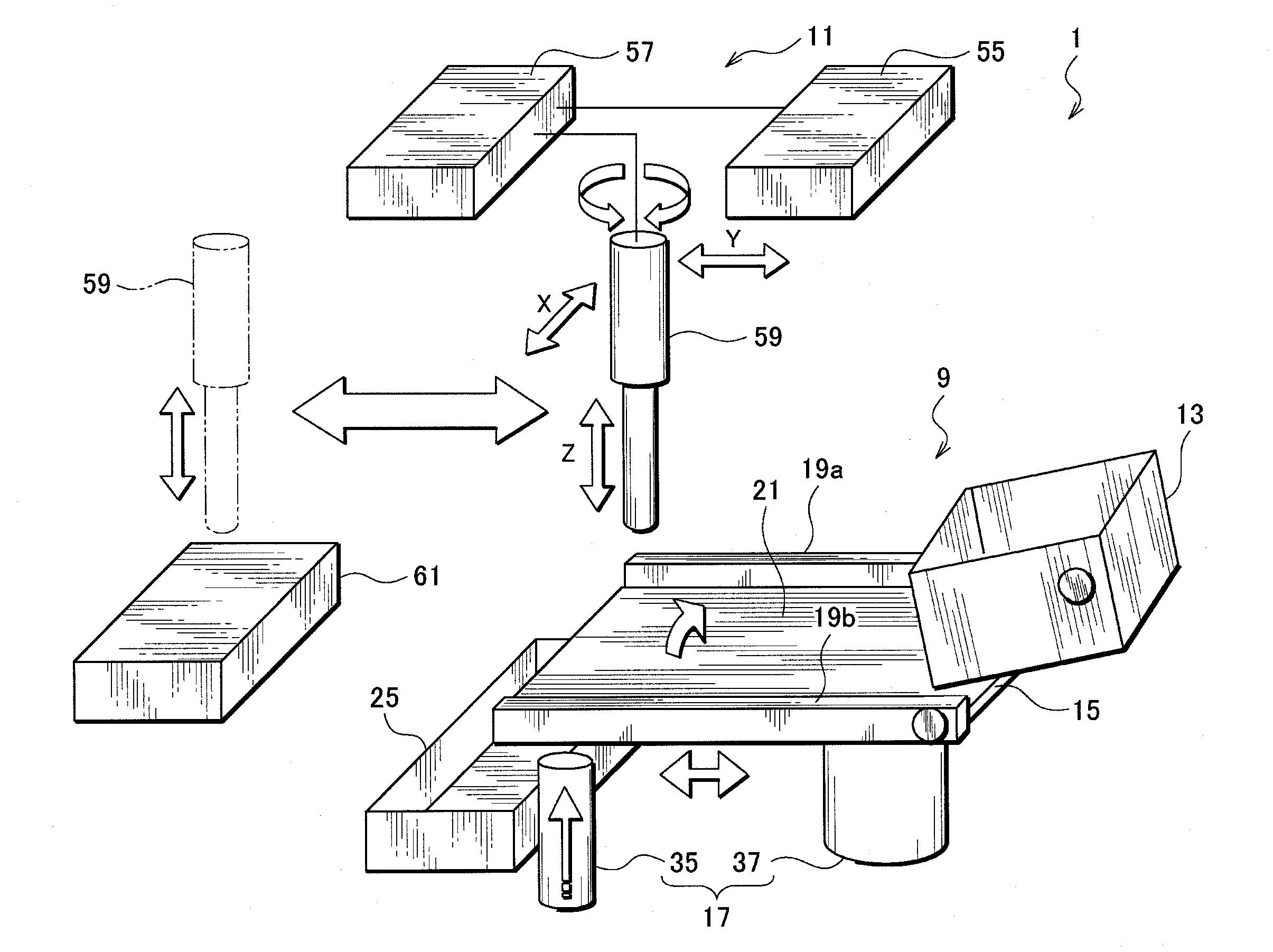
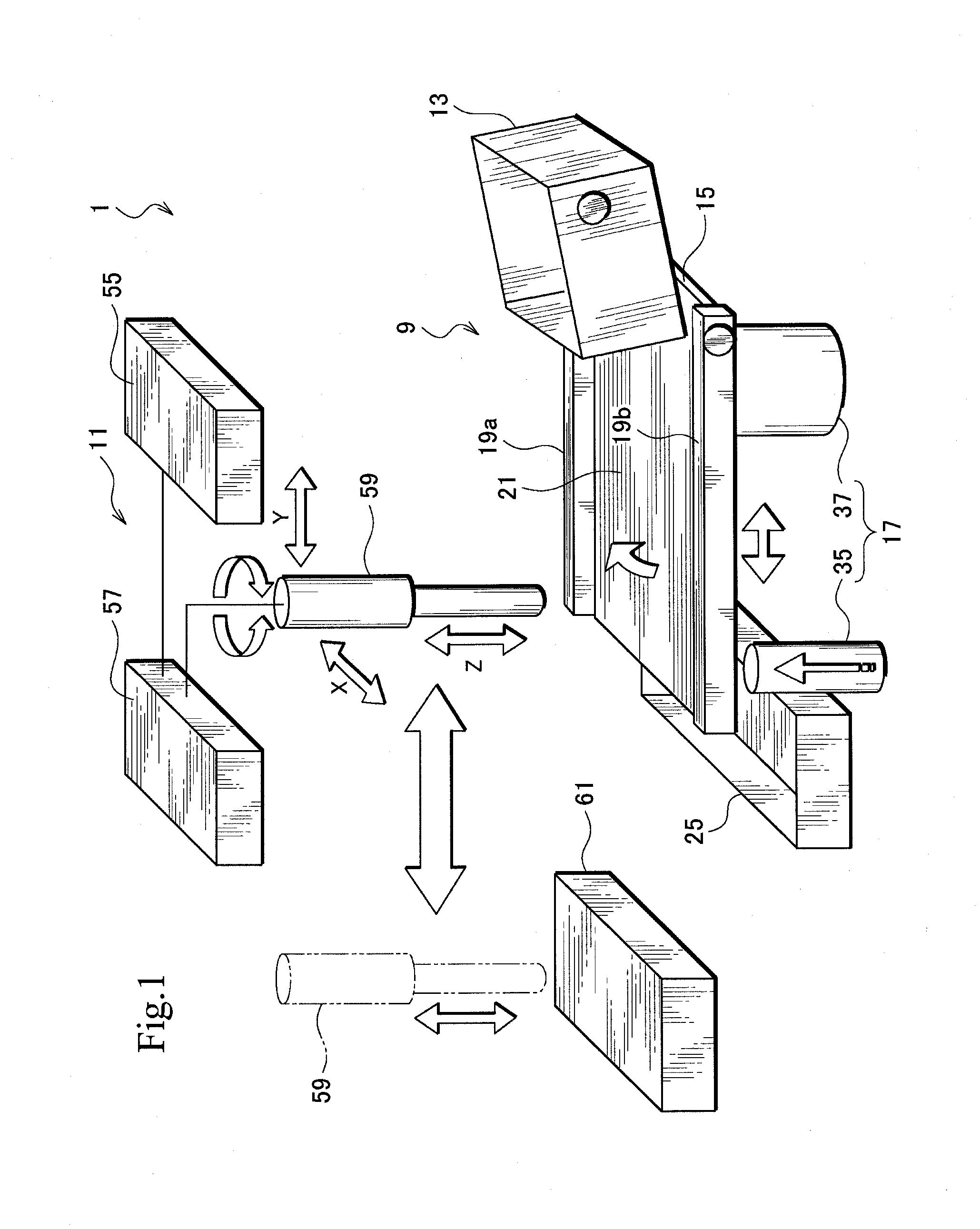
[0022]An embodiment of the present invention will be explained in detail with reference to the drawings. The embodiment applies separate impacts to workpieces to separate the workpieces from one another and adjust them into correct top-bottom orientation. The embodiment individually holds the separated and adjusted workpieces and horizontally aligns the held workpiece while feeding the held workpiece to a destination. With this, the embodiment prevents the workpieces from successively hitting and rubbing one another to produce particles or contaminants.

[0023]The embodiment employs a movable part and a drive part. Preferably, the drive part includes a vertical drive part to apply a single upward or vertical impact to the movable part so that a bouncing force is applied to workpieces placed on the movable part and a horizontal drive part to apply a single forward or horizontal impact to the movable part so that a shifting force is applied to the workpieces. The vertical impact and the...


PUM


Abstract

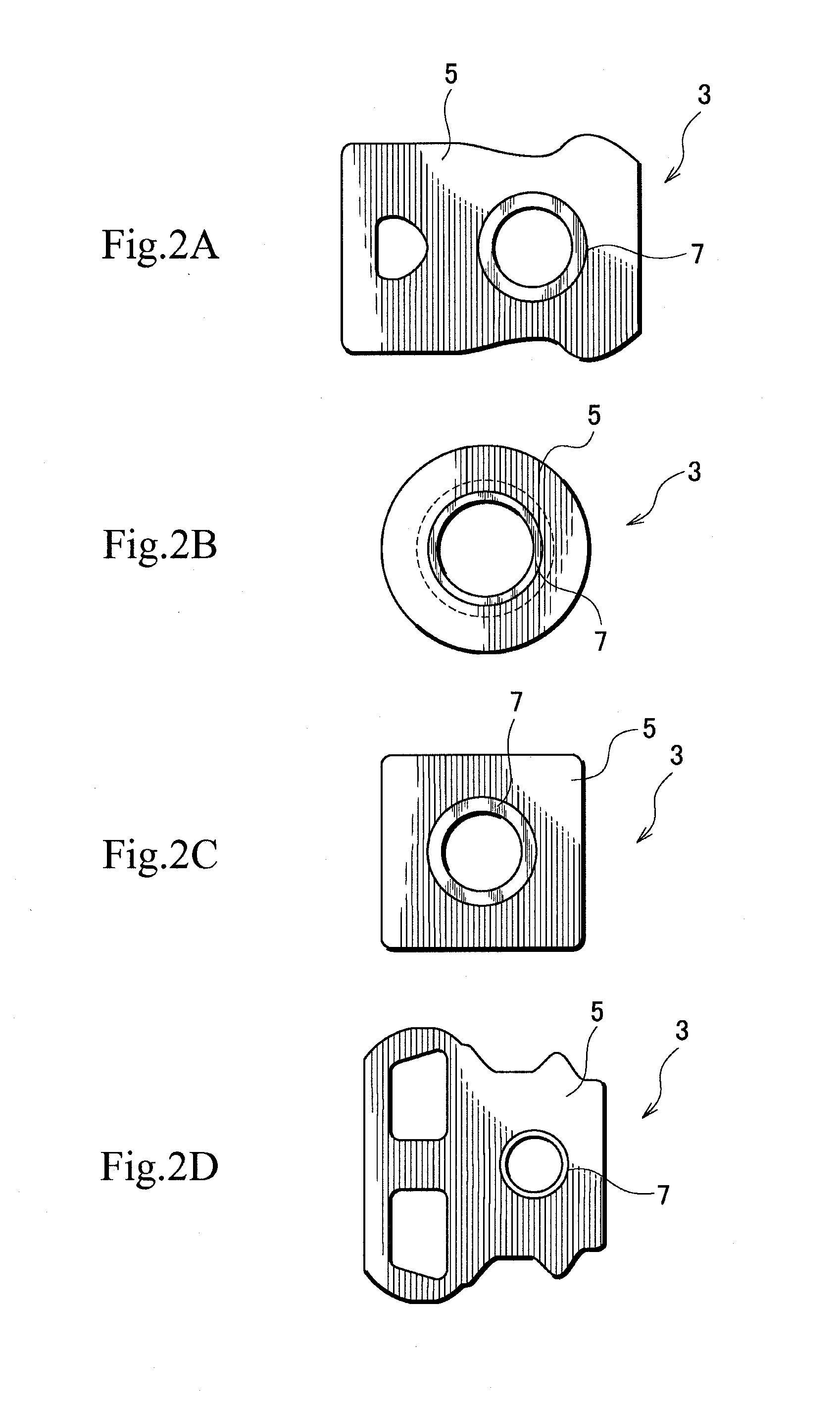
A workpiece feeder includes a forward stage that separates base plates from one another and adjusts the base plates into correct top-bottom orientation and a pickup unit that individually holds the separated and adjusted base plates and horizontally aligns the held base plate into correct planar posture while feeding the held base plate to a destination. The forward stage includes a stage body that has a stage surface on which the base plates are placed and is movably supported so as to shift the stage surface and a drive unit that applies separate impacts to the stage body so that the stage body moves to apply a bouncing force and a shifting force orthogonal to the bouncing force due to the separate impacts to the base plates.

Description

BACKGROUND OF THE INVENTION[0001]1. Field of the Invention[0002]The present invention relates to a workpiece feeder for separating, adjusting, and feeding workpieces and an adjustment-and-separation apparatus used with the workpiece feeder.[0003]2. Description of Related Art[0004]Workpiece feeders or parts feeders are used to feed small workpieces or parts into a production line to assemble the parts into products.[0005]A standard parts feeder employs a vibration bowl. Into the vibration bowl, many parts are charged and the vibration bowl is continuously and finely vibrated to separate and align the parts. The separated and aligned parts are conveyed to a destination.[0006]When many parts are charged into the vibration bowl and are continuously vibrated, the parts hit and rub one another or the bowl, to create dust such as particles and contaminants.[0007]The parts feeder using the vibration bowl is employed in a manufacturing line to manufacture, for example, head suspensions that ...

Claims


Application Information

Patent Timeline
IPC IPC(8): B65G47/24B65G47/248B65G37/00B65G47/14
CPCB65G47/256B65G47/1414
Inventor NAKAJIMA, KAZUMASAHAYASHI, YUKIHIRO
Owner NHK SPRING CO LTD
Learn More