
Method and system for wireless charging in a portable terminal

a portable terminal and wireless charging technology, applied in the field of portable terminals, can solve the problems of rapid consumption of battery power of portable terminals, popularity of these types of functions,

Active Publication Date: 2012-10-04
SAMSUNG ELECTRONICS CO LTD
View PDF6 Cites 279 Cited by
  • Summary
  • Abstract
  • Description
  • Claims
  • Application Information

AI Technical Summary

Benefits of technology

[0009]Exemplary aspects of the present invention address at least some of the problems and/or disadvantages and to provide at least the advantages described below. Accordingly, an aspect of the present invention is to provide a method for enabling a user to wirelessly charge a portable terminal with a level of convenience unknown heretofore.
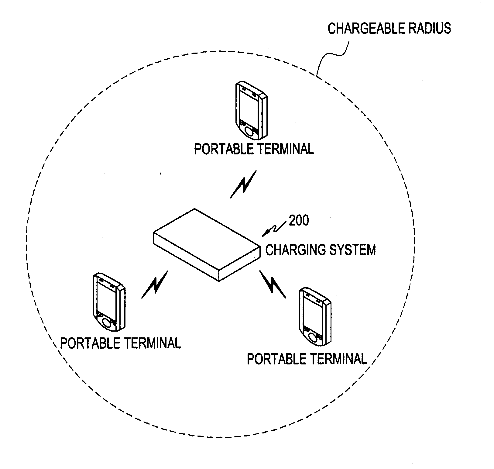
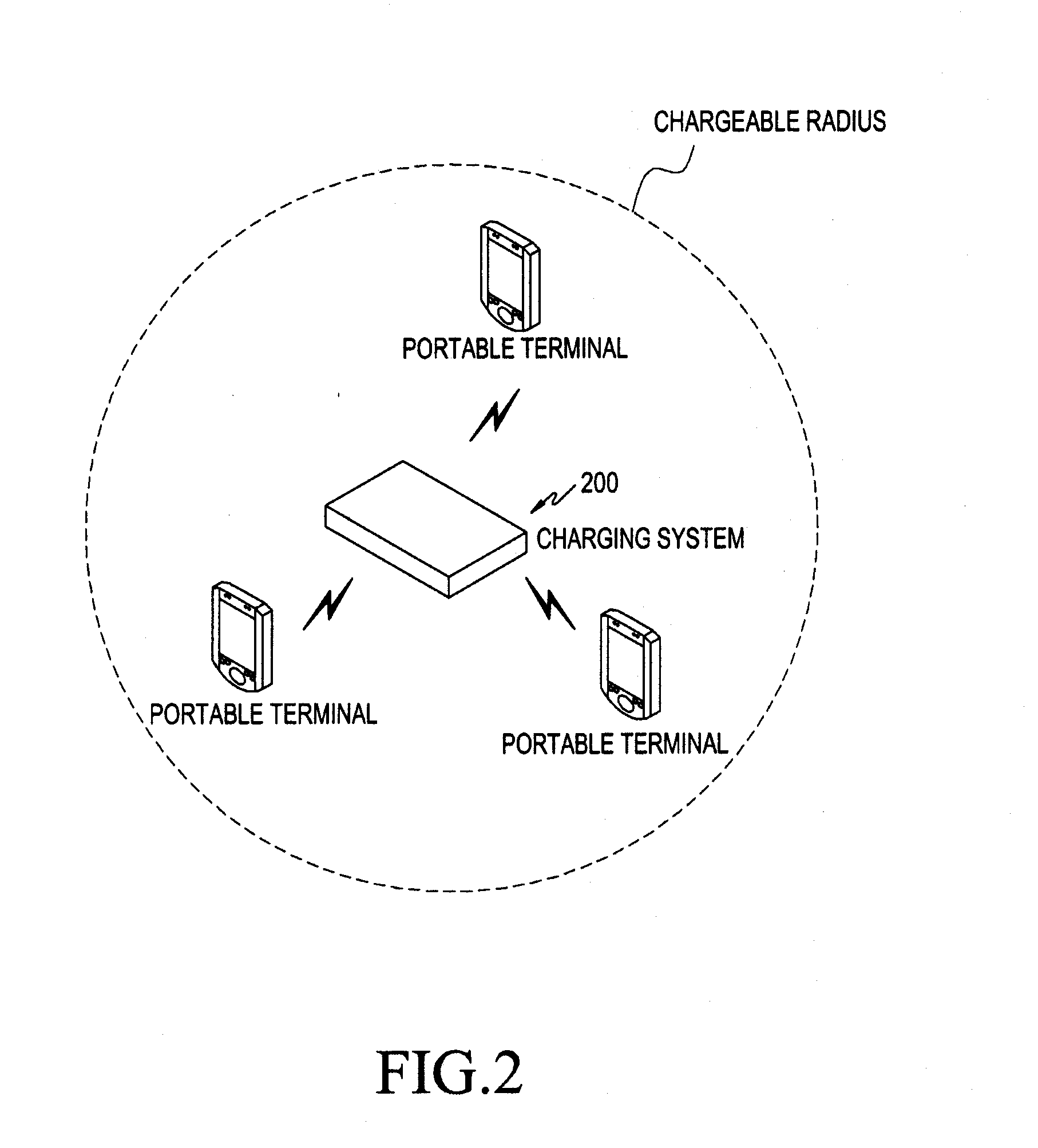
[0010]In accordance with an exemplary embodiment of the present invention, there is provided a method for wirelessly charging a portable terminal using a Radio Frequency (RF), in which a charging system detects one or more portable terminals within a predetermined area, requests information needed for (i.e. associated with) charging to the one or more portable terminals, receives the information associated with charging from each of the one or more portable terminals, selects a portable terminal to be wirelessly charged from among the one or more portable terminals based on the received information regarding charging requirements, and transmits a p

Problems solved by technology

In particular, the inclusion of cameras, data communications, and multimedia play functions in portable terminals coupled with decreased costs for such devices have caused their popularity to soar.
However, the implementation of these types of functions rapidly consumes the battery power of the portable terminals, which were not originally designed for powering such a conglomeration of items.
However, the conventional wireless charging technology just permits wireless charging of a portable terminal which is not a user friendly process, without specifying a user-friendly wireless charging method for a portable terminal

Method used


Image

  • Method and system for wireless charging in a portable terminal
  • Method and system for wireless charging in a portable terminal
  • Method and system for wireless charging in a portable terminal

Examples


Embodiment Construction

[0017]Reference will now be made in detail to the preferred exemplary embodiments of the present invention with reference to the accompanying drawings. The following description is given only of components and / or operations required for a person of ordinary skill in the art to understand the present invention and the other background art will not be described so as not to obscure the subject matter of the present invention.

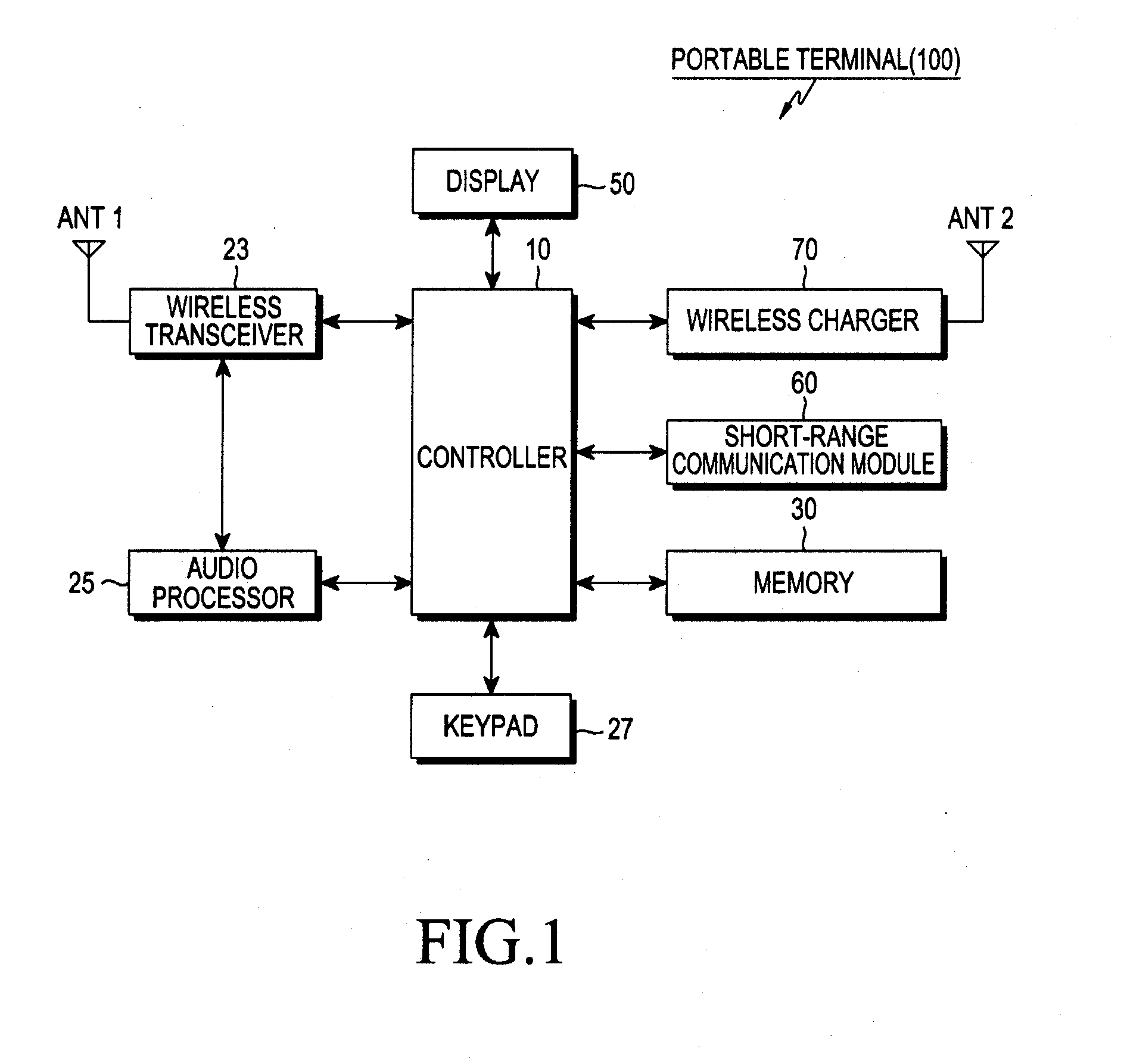
[0018]A portable terminal according to an exemplary embodiment of the present invention comprises a mobile electronic device. The term “portable terminal” used herein covers a broad range of terminals, including but in no way limited to a video phone, a mobile phone, a smart phone, an International Mobile Telecommunications (IMT)-2000 terminal, a Wideband Code Division Multiple Access (WCDMA) terminal, a Universal Mobile Telecommunication System (UMTS) terminal, a Personal Digital Assistant (PDA), a Portable Multimedia Player (PMP), a Digital Multimedia Broadcasti...


PUM


Abstract

A method for wirelessly charging a portable terminal using a Radio Frequency (RF) is provided. A charging system detects one or more portable terminals within a predetermined area, and preferably requests information needed for charging to the one or more portable terminals via short-range communication, receives the information in response needed for charging from each of the one or more portable terminals. A portable terminal to be wirelessly charged from among the one or more portable terminals is selected, based on the received information needed for charging, and the charging system transmits a predetermined RF for charging to the selected portable terminal.

Description

CLAIM OF PRIORITY[0001]This application claims priority under 35 U.S.C. §119(a) to a Korean Patent Application filed in the Korean Intellectual Property Office on Mar. 30, 2011 and assigned Serial No. 10-2011-0029124, the contents of which are incorporated herein by reference in its entirety.BACKGROUND OF THE INVENTION[0002]1. Field of the Invention[0003]The present invention relates to a portable terminal, and more particularly, to a method and system for wireless charging the battery in a portable terminal[0004]2. Description of the Related Art[0005]Due to the development of various, convenient functions of tablet PCs such as Galaxy Tab, the i-Pad and smart phones, the proliferation of such portable terminals have been widespread.[0006]In particular, the inclusion of cameras, data communications, and multimedia play functions in portable terminals coupled with decreased costs for such devices have caused their popularity to soar. However, the implementation of these types of funct...

Claims


Application Information

Patent Timeline
IPC IPC(8): H02J7/00
CPCH02J7/025H02J7/00045H02J50/20H02J50/80H02J50/40G06F1/3212H02J50/90H02J7/0048H02J2310/22
Inventor SON, IN-GUKANG, CHANG-TAEK
Owner SAMSUNG ELECTRONICS CO LTD
Learn More