
Depinching mechanism for paper jam removal in printer

a technology of paper jam removal and pinching mechanism, which is applied in the field of printers, can solve the problems of paper jam, paper skew or paper jam, paper jam, etc., and achieve the effect of facilitating the user to remove paper jam in the printer

Inactive Publication Date: 2012-10-04
CAL COMP ELECTRONICS +1
View PDF9 Cites 1 Cited by
  • Summary
  • Abstract
  • Description
  • Claims
  • Application Information

AI Technical Summary

Benefits of technology

[0007]Accordingly, the present invention is directed to a depinching mechanism which facilitates the user to remove paper jam in printers.
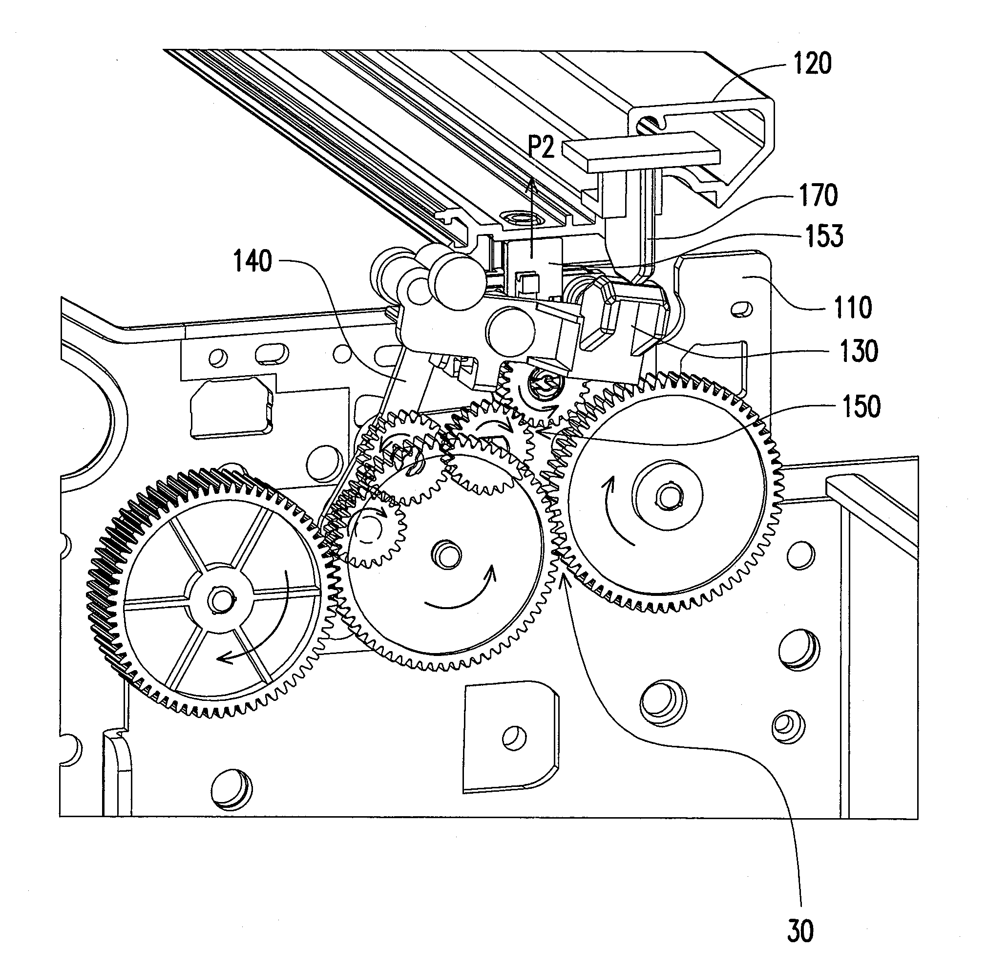
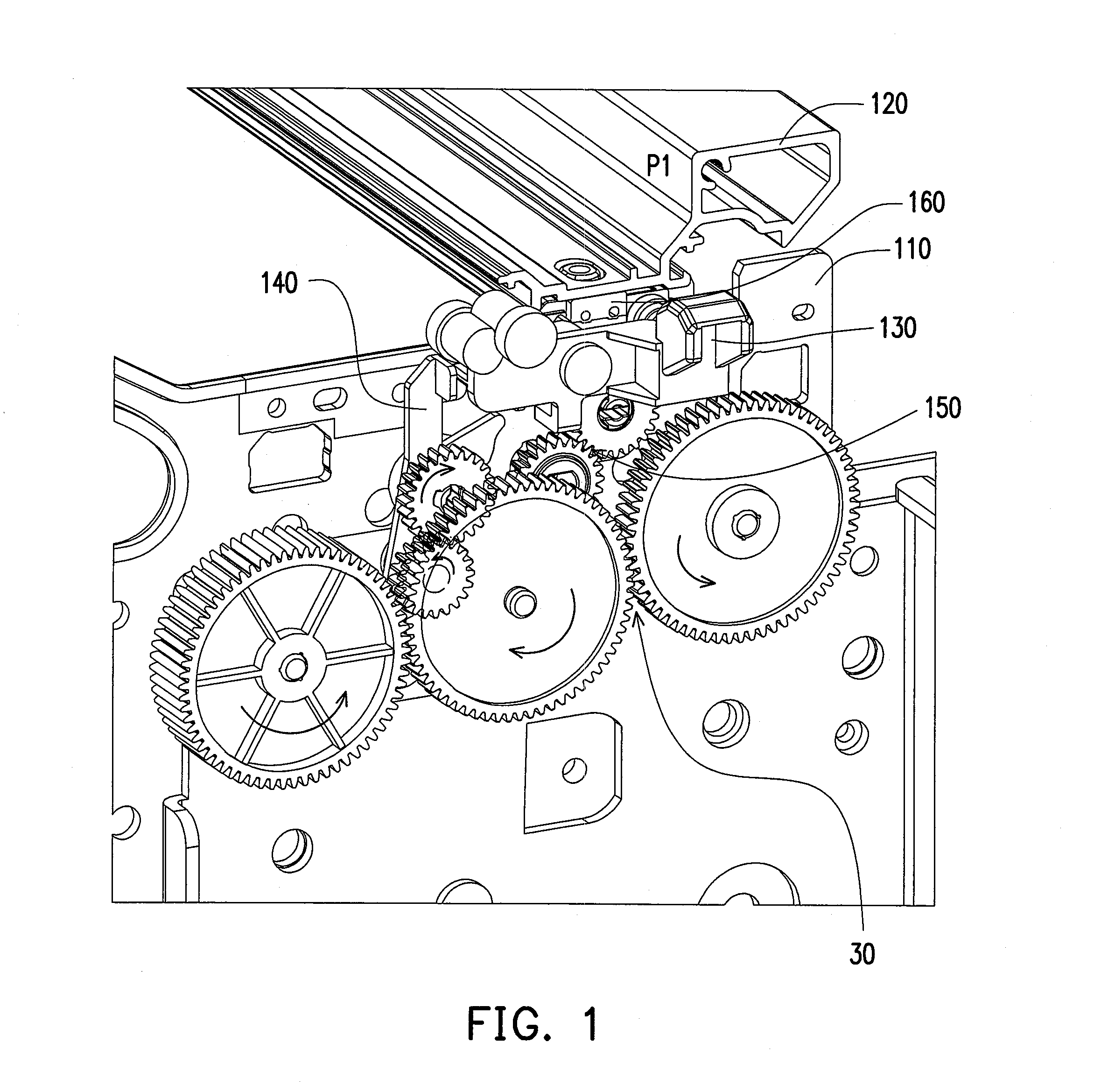
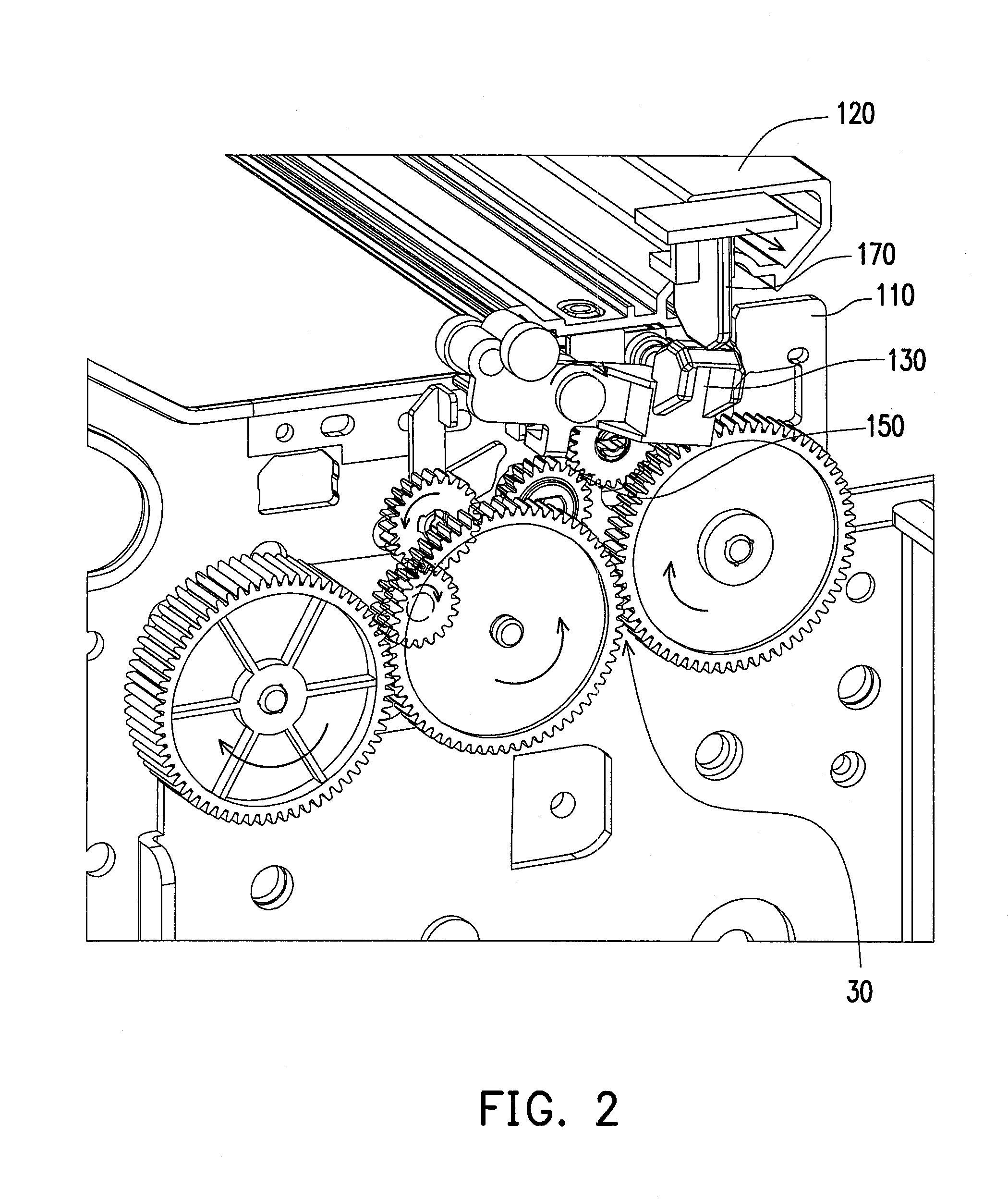
[0016]More particular, during normal printing process, the depinching mechanism is in the idle status, and the feed rollers of the printer rotate in a forward direction. Once the firmware of the printer senses a paper jam, it will tell the feed rollers to rotate in a reverse direction and at the meanwhile it will tell the carriage to move to a predetermined position to trigger the trigger arm. And then the depinching mechanism starts to work as follows: The trigger arm slides and pushes down on the slope of the limiter arm and thus the limiter arm rotates clock wise. This action will free the rocker arm to rotate clock wise. And then, the rocker arm engages with the lifting device to transmit a torque to the lifting device. And once the lifting device is engaged with the rocker arm, the gear-cam starts to rotate. Then, the gear-cam lifts the star wheel assembly from the first position to the second position and lowers the star wheel assembly from the second position to the first position by means of the predetermined profile in its outer race of the gear-cam. And the user can easily and conveniently remove the jammed paper while the star wheel assembly is lifted.
[0017]After the jammed paper is removed, the firmware will tell the feed rollers to rotate forward. And since the rocker arm is coupled to the gear which drives the feed rollers, the rocker arm will disengage with the lifting device when the feed rollers rotate forward. At the meanwhile, the trigger arm will free the limiter arm from pushing down on it. And the limiter arm rotates back to its original position (horizontal) by its own weight. Then, once the limiter arm is back to its original position, the limiter arm prevents the rocker arm to enable the lifting device. In this way, the depinching mechanism gets into the idle status again and the feed rollers rotate forward and ready for normal printing process.
[0018]In view of the above, according to the embodiments of the present invention, through the depinching mechanism, when paper jam occurs, the star wheel assembly is lifted to the second position from the first position and lowered to the first position. The depinching mechanism is in the idle status during normal printing process. And thus, the depinching mechanism can facilitate the user to remove jammed paper when paper jam occurs.

Problems solved by technology

However, during a paper picking process of the printer, a phenomenon of paper skew or paper jam is occurred due to a mechanical structure of the printer and differences of paper properties.
It is rather inconvenient and time consuming that paper jam occurs during printing or receiving a fax.
Usually paper jams when the transferring paper is clamped by the fixing roller and the pressure roller.
If the paper tears when removing it from the feeding rollers, the torn pieces of paper may get stuck within the feeding rollers.
And if the printer continues working with any torn pieces of paper remain inside the feeding rollers, more paper jams are likely to occur.
Hands may also get dirty to remove the jammed paper if the paper is jammed within the paper feeding device.

Method used


Image

  • Depinching mechanism for paper jam removal in printer
  • Depinching mechanism for paper jam removal in printer
  • Depinching mechanism for paper jam removal in printer

Examples


Embodiment Construction

[0027]Reference will now be made in detail to the present preferred embodiments of the invention, examples of which are illustrated in the accompanying drawings. Wherever possible, the same reference numbers are used in the drawings and the description to refer to the same or like parts.

[0028]The figures are not drawn to scale and they are provided merely to illustrate the present invention. Several aspects of the invention are described below with reference to example applications for illustration. It should be understood that numerous specific details, relationships and methods are set forth to provide a full understanding of the invention. The present invention may be embodied in many different forms and should not be construed as limited to the embodiments set forth herein. For example, the present invention can be embodied as a method or a system.

[0029]The present invention provides a depinching mechanism with a simple mechanism and low manufacturing cost in order to solve the ...


PUM


Abstract

A depinching mechanism including a frame, a star wheel assembly, a limiter arm, a rocker arm and a sensor is provided in present invention. Through the depinching mechanism the star wheel assembly is lifted from the first position to the second position when paper jam occurs, and thus depinched the media the user can clear the paper jam. And after that the star wheel assembly is lowered from the second position to the first position. The star wheel assembly remains in the first position in the normal printing process. Since when paper jam occurs the star wheel assembly is lifted by the depinching mechanism, the user can easily and conveniently remove the jammed paper. And thus, the depinching mechanism can facilitate the user to remove jammed paper when paper jam occurs in printer. Thus, the depinching mechanism can be used in printers to solve the paper jamming problems.

Description

CROSS-REFERENCE TO RELATED APPLICATION[0001]This application claims the priority benefit of Singapore application serial no. 201102298-5, filed on Mar. 31, 2011. The entirety of the above-mentioned patent application is hereby incorporated by reference herein and made a part of this specification.BACKGROUND OF THE INVENTION[0002]1. Field of the Invention[0003]The present invention generally relates to printers and more particularly to a depinching mechanism which facilitates users to remove the jammed paper in printers.[0004]2. Description of Related Art[0005]Along with the widespread of information products, various information products are developed, and the information products have a general trend of diversity. However, regarding image display methods of a computer, displays and printers are mainly used as image output devices. Wherein, the printers can be approximately categorized into three types of point matrix printers, inkjet printers and laser printers. Taking the laser pr...

Claims


Application Information

Patent Timeline
Patent Type & Authority Applications(United States)
IPC IPC(8): B65H7/02
CPCB65H7/06B65H2403/532B65H2404/1442B65H2511/528B65H2513/40B65H5/062B65H2601/11B65H2220/01B65H2220/02
Inventor CHNG, CHOW-JINTHENG, FOO-YINTOH, CHER-LEK
Owner CAL COMP ELECTRONICS
Learn More