
FIR Filter with Reduced Element Count

a filter and element count technology, applied in filters, digital technique networks, instruments, etc., can solve the problem of limiting the use of the circuit of fig. 1, and requiring a negative resistance value which cannot be constructed directly

Active Publication Date: 2012-09-27
ESS TECHNOLOGY
View PDF3 Cites 6 Cited by
  • Summary
  • Abstract
  • Description
  • Claims
  • Application Information

AI Technical Summary

Problems solved by technology

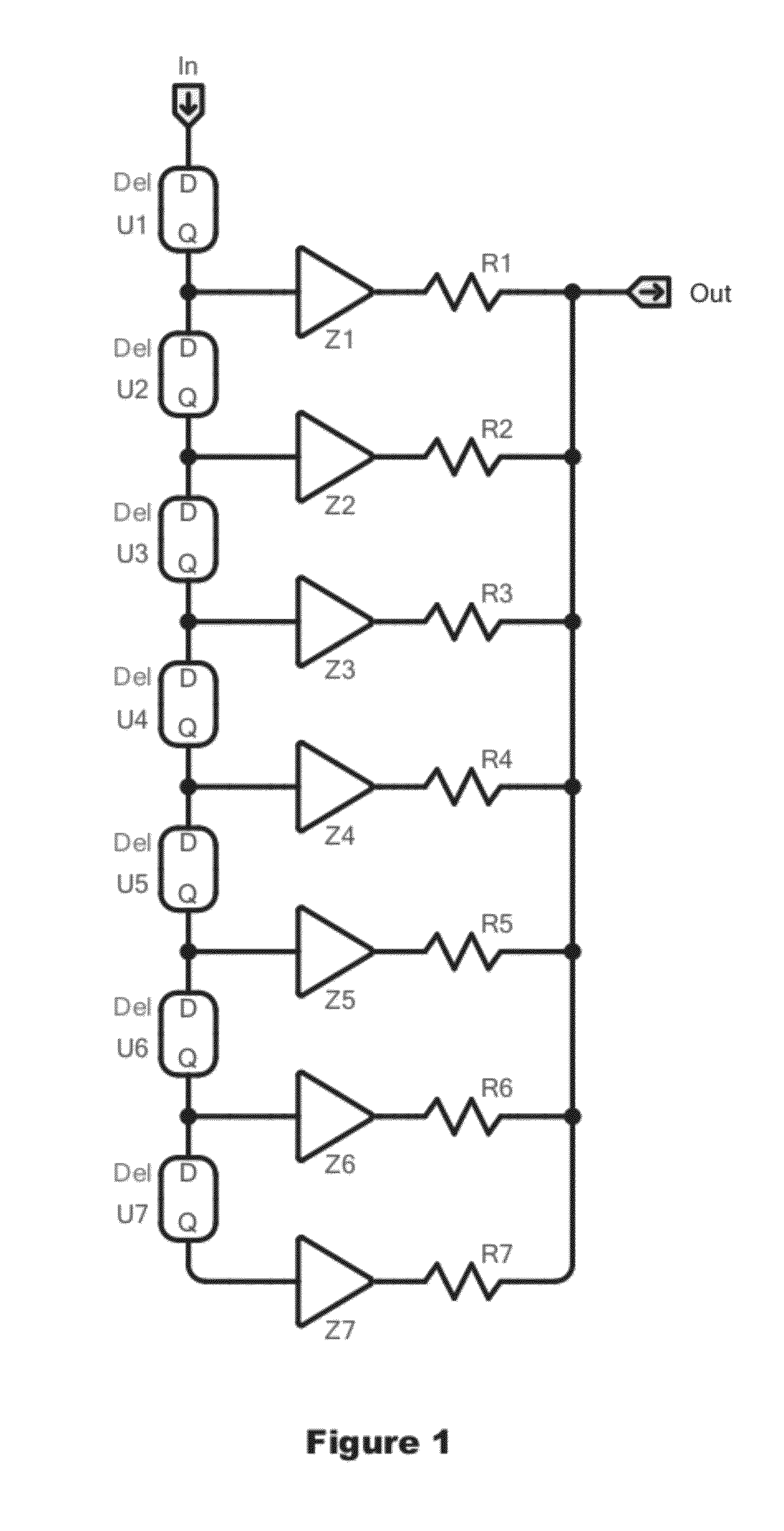
One limitation of the circuit of FIG. 1 is that while the output is the weighted sum of the delayed signal, the weights all have to be positive numbers, as the circuit as shown does not have the ability to implement negative coefficients.
This limits the use of the circuit of FIG. 1, since while most of the Fourier coefficients for a desired frequency response will be positive numbers, even for an output considered positive some coefficients may be negative, requiring a negative resistance value which cannot be constructed directly.

Method used


Image

  • FIR Filter with Reduced Element Count
  • FIR Filter with Reduced Element Count
  • FIR Filter with Reduced Element Count

Examples


Embodiment Construction

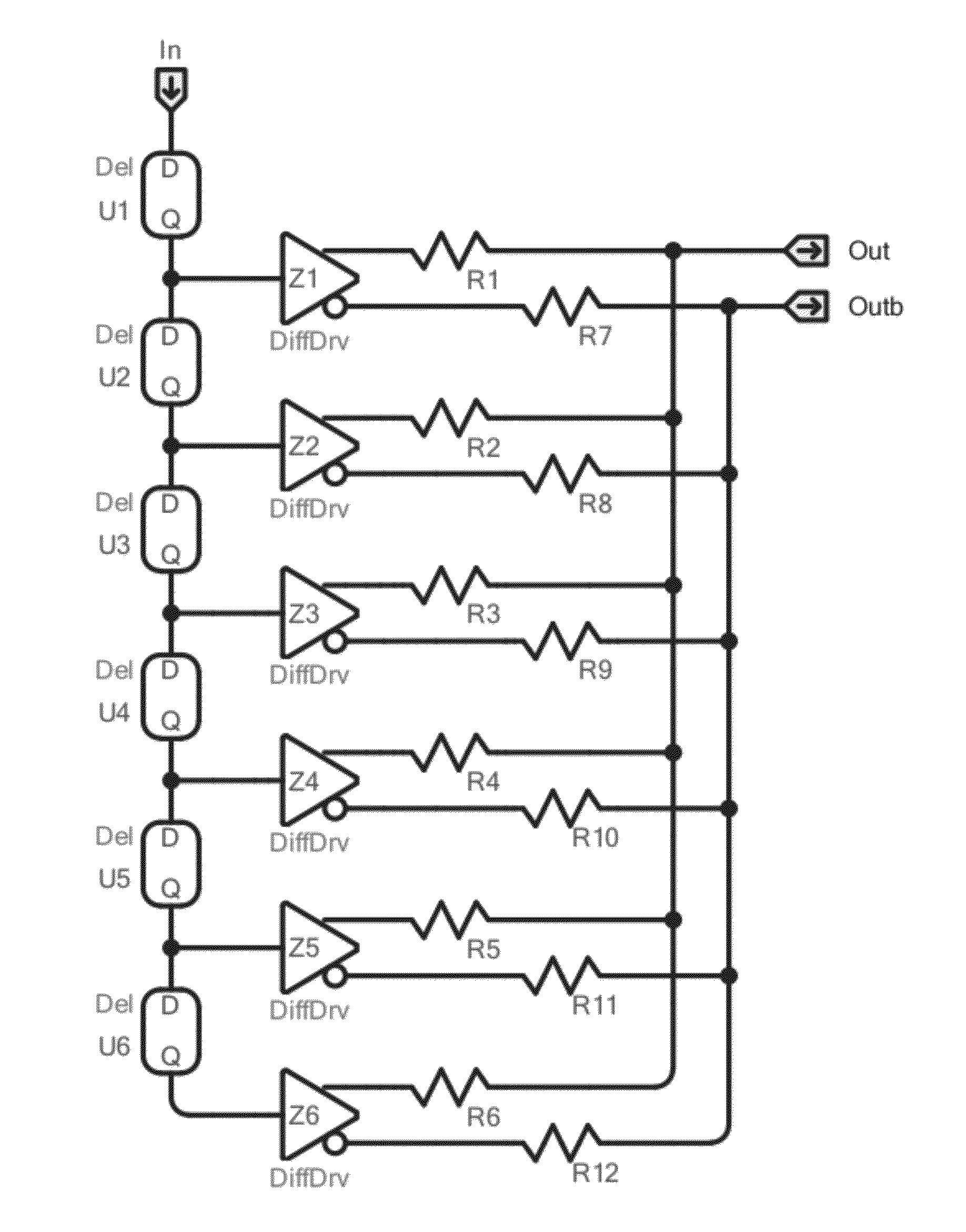
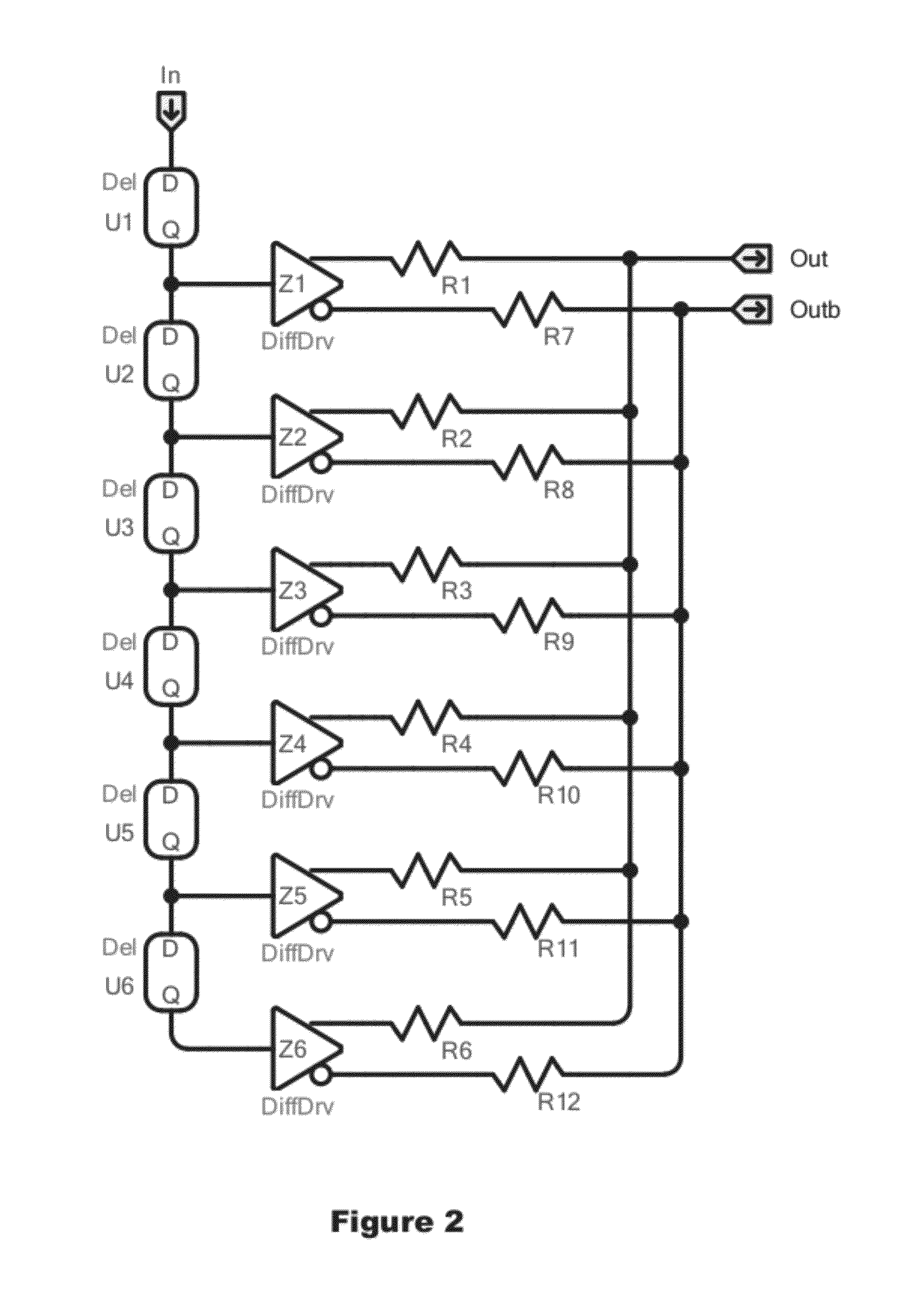
[0027]The present application describes a finite impulse response (FIR) filter having a differential output and capable of having negative coefficients using only the same number of resistors as in the non-differential case, e.g., approximately half the number of resistors as is commonly used in the prior art, and a method of designing such a filter.

[0028]One output signal of the differential output is created by using impedance devices corresponding to approximately one-half the Fourier coefficients that create a desired frequency response; the complement signal is created by using impedance devices corresponding to approximately the other half of the Fourier coefficients for the desired frequency response. Given the number of Fourier coefficients typically used in the art, using this number of impedance devices provides a signal that is substantially the same as if impedance devices corresponding to all of the coefficients were used. The method also uses a delay line that repeated...


PUM


Abstract

A finite impulse response (FIR) filter having a differential output and capable of having negative coefficients, and a method of designing the filter, is disclosed. In contrast to the prior art, in which two output signals requires the use of two identical sets of impedance devices corresponding to the Fourier coefficients that create the desired response of the filter, the described method and system uses only a single set of impedance devices, and thus approximately one-half of the number of impedance devices used in the prior art. This is accomplished by appropriately selecting which resistors contribute to which output, so that a differential output may be obtained that is substantially the same as if impedance devices corresponding to all of the coefficients were used for each signal.

Description

[0001]This application claims priority from Provisional Application No. 61 / 466,424, filed Mar. 22, 2011, which is incorporated by reference in its entirety.FIELD OF THE INVENTION[0002]The present invention relates generally to electronic filters, and more particularly to finite impulse response (FIR) filters.BACKGROUND OF THE INVENTION[0003]A finite impulse response (FIR) filter is a type of electronic filter with a broad range of applications. FIR filters are widely used in both digital signal processing and digital video processing, and their construction is well known in the prior art.[0004]One type of FIR filter is a transversal filter, or tapped delay line filter, as shown in FIG. 1. The output of such a filter is a weighted combination of voltages taken from uniformly spaced taps, and thus a weighted sum of the current input value and a finite number of previous values of the input. The output is proportional to the sum of the delayed voltages divided by the resistances connec...

Claims


Application Information

Patent Timeline
IPC IPC(8): G06F17/10G06F7/523
CPCH03H15/00H03H17/06
Inventor MALLINSON, A. MARTIN
Owner ESS TECHNOLOGY
Learn More