
Gas combustor and safety actuating device thereof

a technology of safety actuation and gas combustor, which is applied in the direction of burners, combustion types, combustion processes, etc., can solve the problems of increased assembly procedure, increased labor force, and difficulty in design, and achieves the effect of rapid assembly function

Active Publication Date: 2012-09-27
TSAI CHIH LIN
View PDF4 Cites 9 Cited by
  • Summary
  • Abstract
  • Description
  • Claims
  • Application Information

AI Technical Summary

Benefits of technology

[0008]One primary object of the present invention is to provide a gas combustor, wherein an ignition device and a combustion device being modularized and having a rapid assembly function and capable of being further installed with a safety actuating device, and overcoming the shortage of custom fabricating positioning members on the inner wall of a housing for each device.
[0014]Another object of the present invention is to provide a safety device used in a gas customer, with designs for simplifying components, the complicated fixing and fastening procedure is avoided and the labor force is effectively saved.

Problems solved by technology

However, when the dimension or shape of the housing is charged, the relative locations of the positioning members installed inside have to be rearranged, and the difficulty during designing is therefore caused.
As such, how to modularize the ignition device and the flame device of a gas combustor is an issue which shall be concerned by skilled people in the arts.
Because the safety actuating device is very small in volume, the screw fitting operation not only increases the assembly procedure but also consumes more labor force.

Method used


Image

  • Gas combustor and safety actuating device thereof
  • Gas combustor and safety actuating device thereof
  • Gas combustor and safety actuating device thereof

Examples


Embodiment Construction

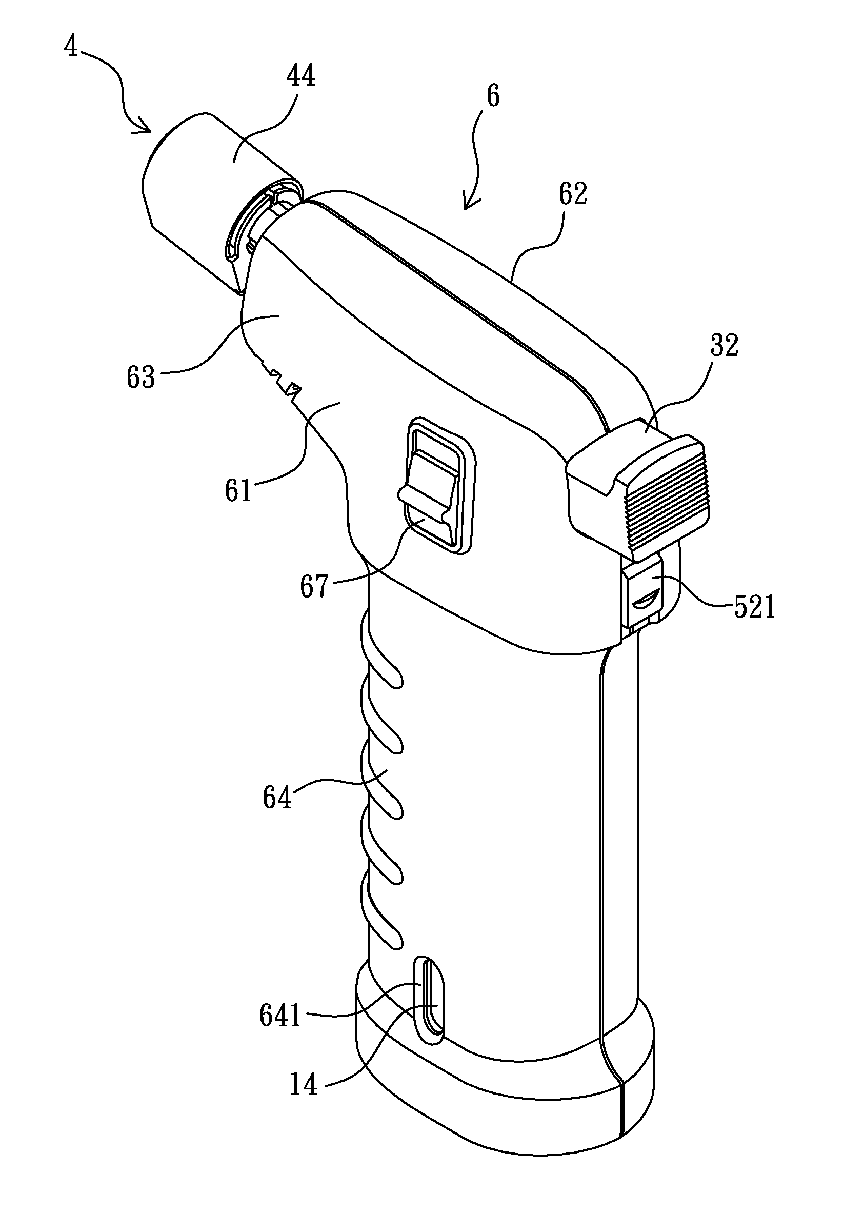
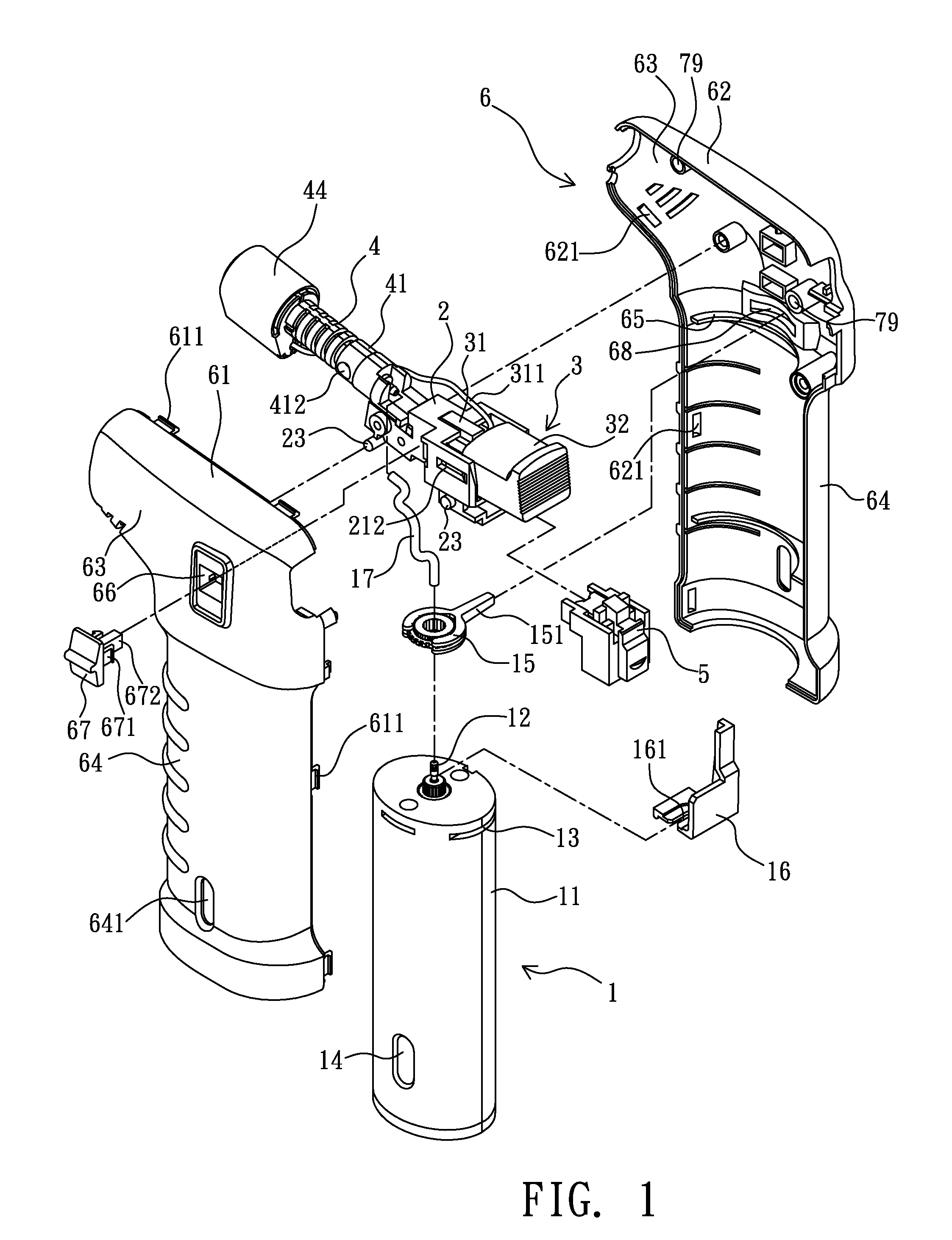
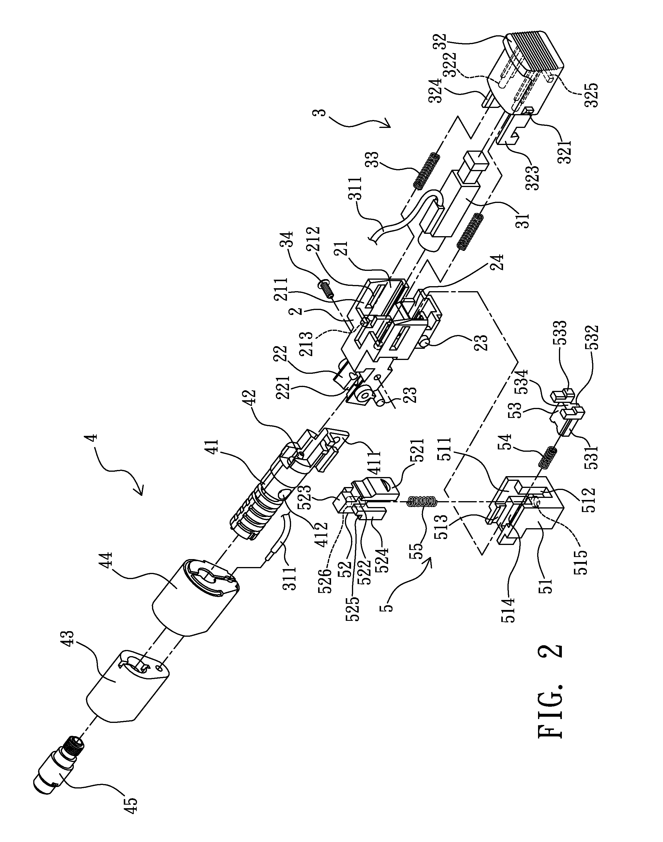
[0028]As shown in FIG. 1 and FIG. 2, the gas combustor provided by the present invention substantially comprises a storage tank 1, a connection seat 2, an ignition device 3, a combustion device 4, a safety actuating device 5 and a housing 6.

[0029]The storage tank 1 is a container for storing liquid gas, and the bottom and the top of a tank body 11 thereof are respectively installed with a conventional filling nozzle (not shown in figures) and a gas discharge nozzle 12. Moreover, the periphery of the upper portion of the tank body 11 is installed with a positioning slot 13, and the lower portion of the tank body 11 is installed with at least an elongated viewing window 14, e.g. a pair of viewing windows 14 symmetrically installed, for conveniently observing the residual amount of the liquid gas in the storage tank 1.

[0030]The gas discharge nozzle 12 is sleeved with a gas regulation ring 15, and a regulation rod 151 laterally extended from the gas regulation ring 15 protrudes from a p...


PUM


Abstract

The present invention relates to a gas combustor, which comprises a storage tank, a connect seat allowing an ignition device and a combustion device to be installed, and a housing. The rear of the connection seat is formed with an accommodation slot in sequence allowing a piezoelectric device of the ignition device and a pressable button member to be installed and positioned, the front of the button member is protruded with a push sheet. Two clamp arms at the front of the connection seat define an insertion slot allowing an insertion tenon fixed at the rear of a mixing tube of the combustion device to be inserted and positioned, such that the mixing tube and the piezoelectric device are in contact. The mixing tube is formed with at least an air inlet hole, and the front and the rear thereof are respectively installed with an ejection nozzle connected to one end of a gas conveying tube and a flame nozzle, and an electric conduction wire of the piezoelectric device is arranged at the periphery of the flame nozzle at intervals. Through pressing the button member, the gas discharge nozzle of the storage tank is enabled to supply combustion gas, and the electric conduction wire at the lateral side of the flame nozzle generates static electric sparks for igniting the mixed combustion gas ejected from the flame nozzle.

Description

BACKGROUND OF THE INVENTION[0001]1. Field of the Invention[0002]The present invention relates to a gas combustor, especially to a gas combustor having a rapid assembly function through a modularization design. The present invention further provides a safety actuating device used in a gas combustor.[0003]2. Description of Related Art[0004]Fire is a must-have matter in human being's daily life, with fire we can cook food, have lights, even operating casting, melting or welding metals. A gas combustor, e.g. a refillable lighter or portable gas stove, consumes liquid gas for igniting objects or cooking foods. Even at present, the gas combustor still plays an irreplaceable role.[0005]The Taiwan Utility Patent No. M338954 (corresponding to the U.S. Pat. No. 7,850,446) granted to the applicant of the present invention has disclosed a hand-held gas combustion apparatus which comprises a storage tank, a gas discharge device, a housing, an ignition device, a safety actuating device and a flam...

Claims


Application Information

Patent Timeline
Patent Type & Authority Applications(United States)
IPC IPC(8): F23D14/72
CPCF23D14/28F23D2207/00F23D14/72F23D14/465
Inventor TSAI, CHIH-LIN
Owner TSAI CHIH LIN
Learn More