Eureka AIR delivers breakthrough ideas for toughest innovation challenges, trusted by R&D personnel around the world.

Tissue manipulation devices

a technology of tissue manipulation and retraction, which is applied in the field of surgical devices, can solve the problems of difficult, critical and difficult triangulation of the retraction direction, and achieve the effect of improving the accuracy of the retraction

Active Publication Date: 2012-09-20
CILAG GMBH INT
View PDF6 Cites 159 Cited by
  • Summary
  • Abstract
  • Description
  • Claims
  • Application Information

AI Technical Summary

Benefits of technology

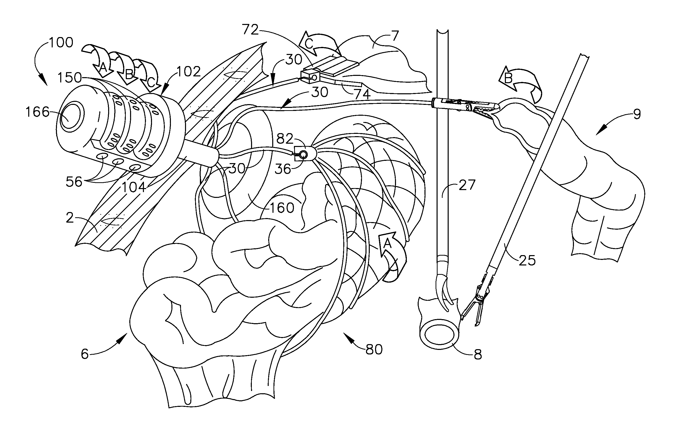
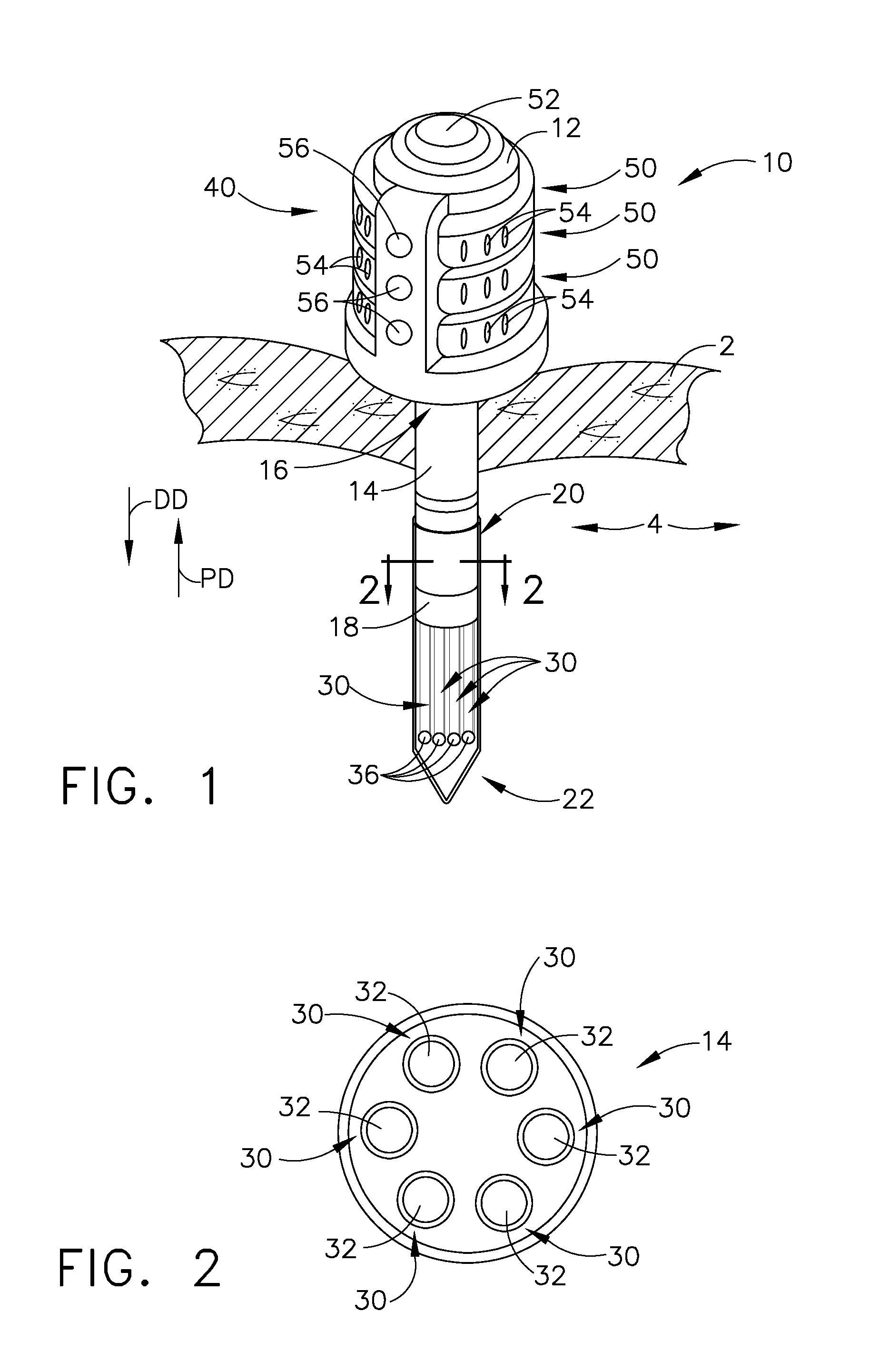
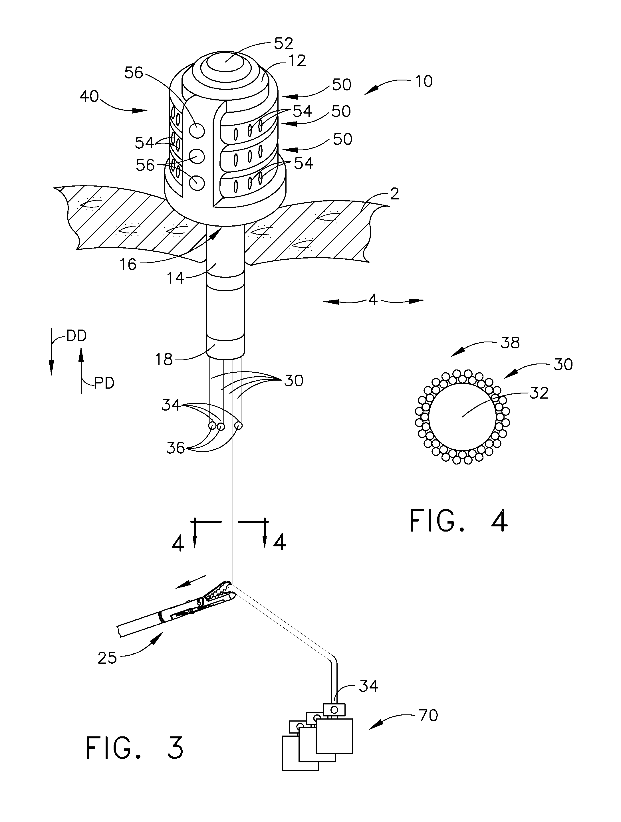
[0009]In connection with yet another general aspect of one form of the present invention, there is provided a tissue manipulation device that comprises a body portion that has a hollow cannula coupled thereto. The hollow cannula has a distal end that is configured to puncture tissue. A first manipulation cable extends through the hollow cannula and is coupled to a first rotatable disc assembly that is operably supported by the body portion such that by rotating the first rotatable disc assembly in a first deployment direction, a first portion of the first manipulation cable is deployed in a first distal direction relative to the distal end of the hollow cannula. By rotating the first rotatable disc assembly in a first actuation direction, the first portion of the first manipulation cable is moved in a first proximal direction relative to the distal end of said cannula. A first releasable lock member interfaces with the first rotatable disc assembly to selectively prevent rotation of the first rotatable disc assembly. A second manipulation cable extends through the hollow cannula. The second manipulation member is coupled to a second rotatable disc assembly that is operably supported by the body portion such that by rotating the second rotatable disc assembly in a second deployment direction, a second portion of the second manipulation cable is moved in a second distal direction relative to the distal end of the hollow cannula. By rotating the second rotatable disc assembly in a second actuation direction, the second portion of the second manipulation cable is moved in a second proximal direction toward the distal end of the cannula. A second releasable lock member interfaces with the second rotatable disc assembly to selectively prevent rotation of the second rotatable disc assembly. A third manipulation cable extends through the hollow cannula. The third manipulation member is coupled to a third rotatable disc assembly that is operably supported by the body portion such that by rotating the third rotatable disc assembly in a third deployment direction, a third portion of the third manipulation cable is moved in a third distal direction relative to the distal end of the hollow cannula. By rotating the third rotatable disc assembly in a third actuation direction, the third portion of the third manipulation cable is moved in a third proximal direction toward the distal end of the cannula. A third releasable lock member interfaces with the third rotatable disc assembly to selectively prevent rotation of the third rotatable disc assembly. At least one surgical tool is removably couplable to a distal end of at least one of the first, second and third manipulation cables. The surgical tool is selected from a group of surgical tools comprising a grasping device and a substantially flexible tissue-retaining net.

Problems solved by technology

One major challenge to employing laparoscopic surgical techniques is the ability to move all of the unrelated or non-involved tissue out of the surgical site to permit better physical and visual access to the target tissue or organ.
A dedicated separation of adjacent tissue structures is often desirable but can be technically difficult due to the limits of instruments that must fit through the working ports.
This is often complicated by the need to move through several quadrants of bowel and otherwise vary the retraction states of tissue over the course of the procedure.
For example, when multiple retraction devices are passed through a single abdomen position, triangulation of the direction of retraction can be very critical and challenging.

Method used


Image

  • Tissue manipulation devices
  • Tissue manipulation devices
  • Tissue manipulation devices

Examples


Embodiment Construction

[0037]The assignee of the present application also owns the following applications which were contemporaneously filed herewith and which are each herein incorporated by reference in their respective entireties:[0038]U.S. patent application Ser. No. ______, filed ______, entitled “Multiple Part Anvil Assemblies For Circular Surgical Stapling Devices”, Attorney Docket No. END6926USNP2 / 110014;[0039]U.S. patent application Ser. No. ______, filed ______, entitled “Modular Surgical Tool Systems”, Attorney Docket No. END6921USNP / 110019;[0040]U.S. patent application Ser. No. ______, filed ______, entitled “Specimen Retraction Devices and Methods”, Attorney Docket No. END6930USNP / 110012;[0041]U.S. patent application Ser. No. ______, filed ______, entitled “Modular Occlusion and Tissue Acquisition Mechanisms For Circular Stapling Devices”, Attorney Docket No. END6932USNP / 110010;[0042]U.S. patent application Ser. No. ______, filed ______, entitled “Collapsible Anvil Plate Assemblies For Circul...


PUM


Abstract

Tissue manipulation and retraction devices. In various forms, the manipulation devices include a cannula that is insertable through the abdominal wall. A plurality of independently controllable manipulation members extend through the cannula and are attachable to various forms of surgical tools. The surgical tools may be manipulated and controlled by a surgeon from a position outside of the patient.

Description

CROSS-REFERENCE TO RELATED APPLICATIONS[0001]This non-provisional patent application claims the benefit of and priority from U.S. Provisional Patent Application Ser. No. 61 / 452,432, filed Mar. 14, 2011, entitled “Surgical Stapling Instruments”, the entire disclosure of which is hereby incorporated by reference.FIELD OF THE INVENTION[0002]The present invention generally relates to surgical devices for temporarily retaining and supporting tissues and organs in a desired orientation during surgery, and more particularly, to devices for retracting tissue that may be inserted through a single port during laparoscopic surgery.BACKGROUND[0003]Minimally invasive surgical procedures are typically conducted through one or more small ports that are inserted through relatively small incisions. Laparoscopic surgery, for example, may involve infusing a gas into a portion of the patient through a small port to facilitate visual access and operating space within the patient. Surgeons may perform va...

Claims


Application Information

Patent Timeline
Patent Type & Authority Applications(United States)
IPC IPC(8): A61B17/28
CPCA61B17/1155A61B17/3417A61B2017/00287A61B2017/07257A61B17/00234A61B2017/00477F04C2270/0421A61B17/068A61B17/07207A61B17/072A61B17/0218A61B17/0293A61B2017/0225A61B2017/0287A61B2017/00353A61B2560/0443
Inventor SHELTON, IV, FREDERICK E.KNIGHT, GARY W.
Owner CILAG GMBH INT
Why Eureka
Eureka Blog
Learn More