
Ophthalmoscope having a laser device

Active Publication Date: 2012-09-20
OD OS
View PDF10 Cites 17 Cited by
  • Summary
  • Abstract
  • Description
  • Claims
  • Application Information

AI Technical Summary

Benefits of technology

[0007]In one aspect, an ophthalmoscope having a laser device for laser treatment of an eye includes an illuminator for illuminating the eye and configured to generate visible and infrared light. The ophthalmoscope also includes a cam

Problems solved by technology

However, most patients find illumination of the eye with visible light to be dazzling and extremely unpleasant so that the patients concerned often react to the illumination with instinctive ocular movements.
These ocular movements considerably complicate observing as well as acquiring an image of the eye.
The ocular movements have a particularly adverse effect on the accuracy with which laser irradiation can be applied to a desired region to be treated, thus causing a considerable risk of unintended irradiation of a sensitive region of the eye.
In addition, ocular movements as a rule require new positioning of a laser beam, which can result in a considerable extension of treatment duration, in particular if a great number of regions of the eye have to be irradiated individually.
However, this leads to irritations of the eye, and as a rule is feasible under local anesthetic only.

Method used


Image

  • Ophthalmoscope having a laser device
  • Ophthalmoscope having a laser device
  • Ophthalmoscope having a laser device

Examples


Embodiment Construction

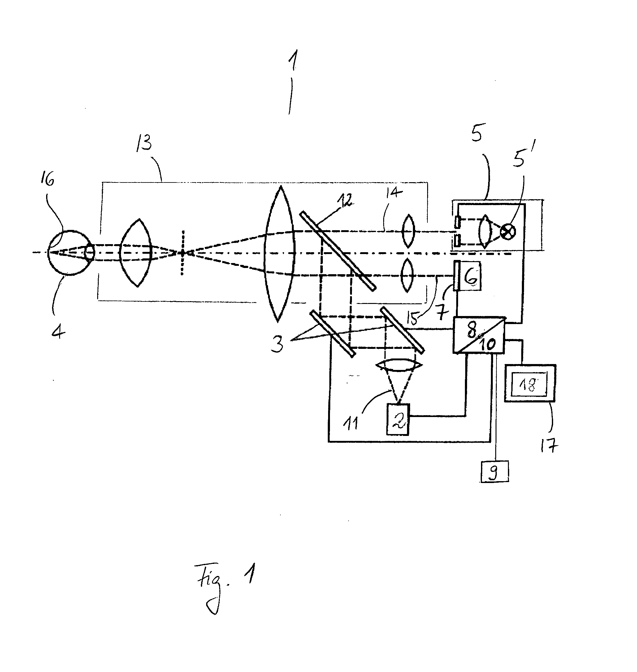
[0016]FIG. 1 shows a schematic representation of a specific embodiment of an ophthalmoscope 1 of the type proposed herein. It comprises a laser device 2 having a beam guiding unit 3 for the laser irradiation of an eye 4. The ophthalmoscope further comprises an illuminator 5 for the illumination of the eye 4 optionally with infrared and / or visible light by means of light-emitting diodes 5′, a camera 6 having a CCD sensor 7 being sensitive to infrared light as well as to visible light, and a control unit 8 connected to the camera 6. The control unit 8 is adapted to trigger the illuminator 5 for generating a light pulse of visible light after a waiting time interval of 200 ms after laser irradiation of the eye 4 with a therapeutic laser beam, and to read out from the camera 6 a control image of the eye 4 acquired by the camera 6 during the light pulse, cf. FIG. 2 to FIG. 5.

[0017]The control unit 8 is further adapted to trigger the illuminator 5 for generating the light pulse also befor...


PUM


Abstract

An ophthalmoscope having a laser device for laser irradiation of an eye, in particular for performing a photocoagulation on fundus of the eye of the eye, includes an illuminator for illuminating the eye as well as a camera for acquiring an image of the eye. The illuminator is adapted to generate visible and infrared lights. The ophthalmoscope further includes a control unit adapted to trigger the illuminator for generating a light pulse of visible light and to read out from the camera a control image of the eye acquired by the camera during the light pulse. The ophthalmoscope is configurable to acquire an image of an eye and perform a laser treatment of an eye.

Description

CROSS-REFERENCE TO RELATED APPLICATION(S)[0001]This application claims priority to U.S. Provisional Application No. 61 / 246,757, filed Sep. 29, 2009, and European Patent Application No. PCT / EP2010 / 006031, filed Sep. 29, 2010, which are herein incorporated by reference in their entirety.TECHNICAL FIELD[0002]The present invention relates to an ophthalmoscope. More particularly, the present invention relates to an ophthalmoscope having a laser device for laser irradiation of an eye and a camera for acquiring an image of the eye.BACKGROUND[0003]Ophthalmoscopes having laser devices are frequently used for the observation and treatment of eyes. Therein, photocoagulation represents an important method of treatment wherein the fundus of the eye, also referred to as fundus, is coagulated or sclerosed. In order to successfully perform such a treatment it is necessary to position a therapeutic laser beam exactly on the region to be treated. Moreover, an effect of a laser treatment on a treated ...

Claims


Application Information

Patent Timeline
IPC IPC(8): A61F9/011A61B3/14
CPCA61B3/12A61B3/14A61F2009/00863A61F2009/00844A61F9/00821A61F2009/00887A61F9/008A61F9/00804A61F2009/00872A61F2009/0087A61B3/0041A61B18/20A61B2017/00057A61F9/00823
Inventor LIESFELD, BENTEIWES, WINFRIEDWEBER, ULRIKEAMTHOR, KAY-UWEKIRSCH, STEPHAN
Owner OD OS
Learn More