
Security apparatus with tether

a technology of security apparatus and tether, which is applied in the direction of electrical apparatus casing/cabinet/drawer, mechanical actuation of burglar alarm, instruments, etc., can solve the problems of further complicating the unauthorized attempt to disarm the security apparatus by changing the passcode, and achieves the effect of complicating the unauthorized attempt to disarm the security apparatus

Inactive Publication Date: 2012-09-13
YANG XIAO HUI
View PDF14 Cites 27 Cited by
  • Summary
  • Abstract
  • Description
  • Claims
  • Application Information

AI Technical Summary

Benefits of technology

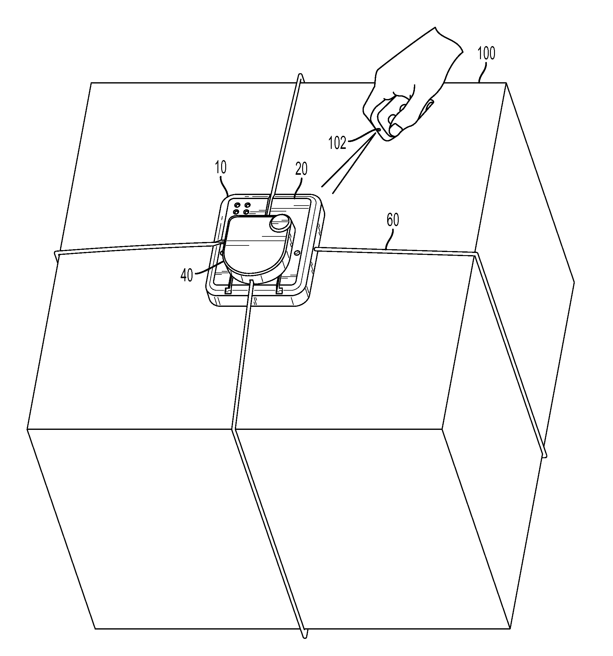
[0013]To install the security apparatus, the base affixes to one side of an object to be protected, and the reel housing is passed around the object, so that the tether wraps around the object. The reel housing then attaches to the base for the physical installation of the security apparatus to the object. The base may have a tether guide on its top so that the tether can be redirected after the first pass around the object so that the tether wraps the object in different directions or planes. The base may have an adhesive element on the bottom to facilitate the attachment of the base to the object.
[0018]Some embodiments of the security apparatus will add another element of security with passcode capabilities in the respective electronics. The security apparatus electronics of these embodiments are capable of storing a passcode which is known to the communication elements of the EAS system and which can be used to confirm to the security apparatus that the disarming signal is authorized. A further element of security can be added by using clock based algorithms to change the passcode synchronously. In those embodiments, the EAS system and the EAS security apparatus both have clock generators and are programmed with the same algorithm and both are programmed with the same initial passcode. As time passes, the algorithm alters the passcode at preset intervals as regulated by the clock generators. This changing passcode further complicates unauthorized attempts to disarm the security apparatus. If a security apparatus tag is detached without being disarmed with the appropriate passcode, the security apparatus will determine an alarm condition exists and generate an alarm.

Problems solved by technology

This changing passcode further complicates unauthorized attempts to disarm the security apparatus.

Method used


Image

  • Security apparatus with tether
  • Security apparatus with tether
  • Security apparatus with tether

Examples


Embodiment Construction

[0028]FIG. 1 is a top perspective view of an object 100 being protected with an embodiment of security apparatus 10 attached. In the embodiment shown in FIG. 1, base 20 is positioned on object 100 and reel housing 40 is joined to base 20. A tether 60 is disposed on a reel within reel housing 40 and a first end 62 of tether 60 is affixed to the reel. Tether 60 extends from reel housing 40, passes around object 100 multiple times, and attaches to base 20 at a second end 64 of tether 60.

[0029]FIG. 2 is a top perspective view of an embodiment of the security apparatus 10. In FIG. 2, tether 60 is withdrawn for the most part into reel housing 40, and base 20 and reel housing 40 are shown in close proximity to each other. Several features may be seen on the top 21 of base 20. Among the more visually prominent features on top 21 of base 20 are tether guide 22, slots 23, and recess 24. These features facilitate the assembly of security apparatus 10 to object 100 and its retention in position...


PUM


Abstract

An electronic article surveillance (EAS) security apparatus is comprised of a base, a reel housing containing a reel, a tether joined to the base and the reel housing and disposed on the reel, and an electronics package. The base attaches to an object to be protected and the tether is wrapped around the object as the reel housing is passed around the object. The reel housing is releasably attached to the base by complimentary coupling elements on each. The base has a tether guide, which allows the tether to be redirected in additional directions as it is wrapped around the object. A releasable blocking mechanism keeps the base and reel housing coupled. The electronics package includes at least a passive EAS element and can contain a microprocessor, wireless communication elements, switches, sound generator, a power supply, and the tether if electrically conductive. The blocking mechanism may be magnetically releasable.

Description

CROSS REFERENCE TO RELATED APPLICATIONS[0001]This application is a continuation-in-part of U.S. application Ser. No. 13 / 177,447 filed on Jul. 6, 2011. U.S. application Ser. No. 13 / 177,447 is a continuation-in-part of U.S. application Ser. No. 13 / 151,106 filed on Jun. 1, 2011, which in turn is a continuation-in-part of U.S. patent application Ser. No. 12 / 815,380 filed on Jun. 14, 2010, and U.S. patent application Ser. No. 13 / 010,571 filed on Jan. 20, 2011. U.S. patent application Ser. No. 12 / 815,380 in turn claims priority to U.S. Provisional Application 61 / 186,889 filed on Jun. 14, 2009. U.S. patent application Ser. No. 13 / 010,571 is a continuation-in-part application based on U.S. patent application Ser. No. 12 / 726,879 filed on Mar. 18, 2010. U.S. patent application Ser. No. 12 / 726,879 is a continuation-in-part application based on U.S. patent application Ser. No. 12 / 498,367, filed on Jul. 7, 2009. U.S. patent application Ser. No. 12 / 498,367 is a continuation-in-part application ba...

Claims


Application Information

Patent Timeline
Patent Type & Authority Applications(United States)
IPC IPC(8): G06F1/16H05K7/00
CPCB65D63/14B65D2101/00G08B13/2434G08B13/1463B65D2203/12B65D2401/00
Inventor YANG, XIAO HUI
Owner YANG XIAO HUI
Learn More