
Bionic telescopic matrix unit

Inactive Publication Date: 2012-09-13
ZHAO DEZHENG
View PDF10 Cites 12 Cited by
  • Summary
  • Abstract
  • Description
  • Claims
  • Application Information

AI Technical Summary

Benefits of technology

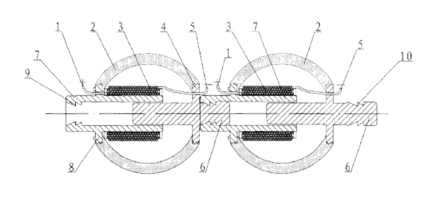
[0013]Each telescopic matrix unit can be lined up from end to end. This means that the front end of the slide shaft (6) of one telescopic matrix unit can be connected to the rear end of the metal guide pipe (7) of an adjacent telescopic matrix unit to create a bionic telescopic chain. Bionic telescopic chains can be linked together to create a bionic telescopic tissue. Specifically, in a bionic telescopic tissue the electromagnetic coil (3) of each bionic telescopic matrix unit is connected in parallel with each other unit to form the two input terminals to be appropriately connected to the power supply of said bionic telescopic tissue. These two input terminals shall be matched with the power supply. Of course, in two adjacent bionic telescopic chains, the telescopic matrix units in one bionic telescopic chain are arranged in a staggered manner relative to the telescopic matrix units of the other bionic telescopic chain. Furthermore, these two chains can be connected by using a flexible soft artificial bionic material to make it structurally more compact and inseparable.

Problems solved by technology

This limits joint related activities in the mechanical arms of those robots.
Consequently, their flexibility is limited.

Method used


Image

  • Bionic telescopic matrix unit
  • Bionic telescopic matrix unit
  • Bionic telescopic matrix unit

Examples


embodiment

PREFERRED EMBODIMENT

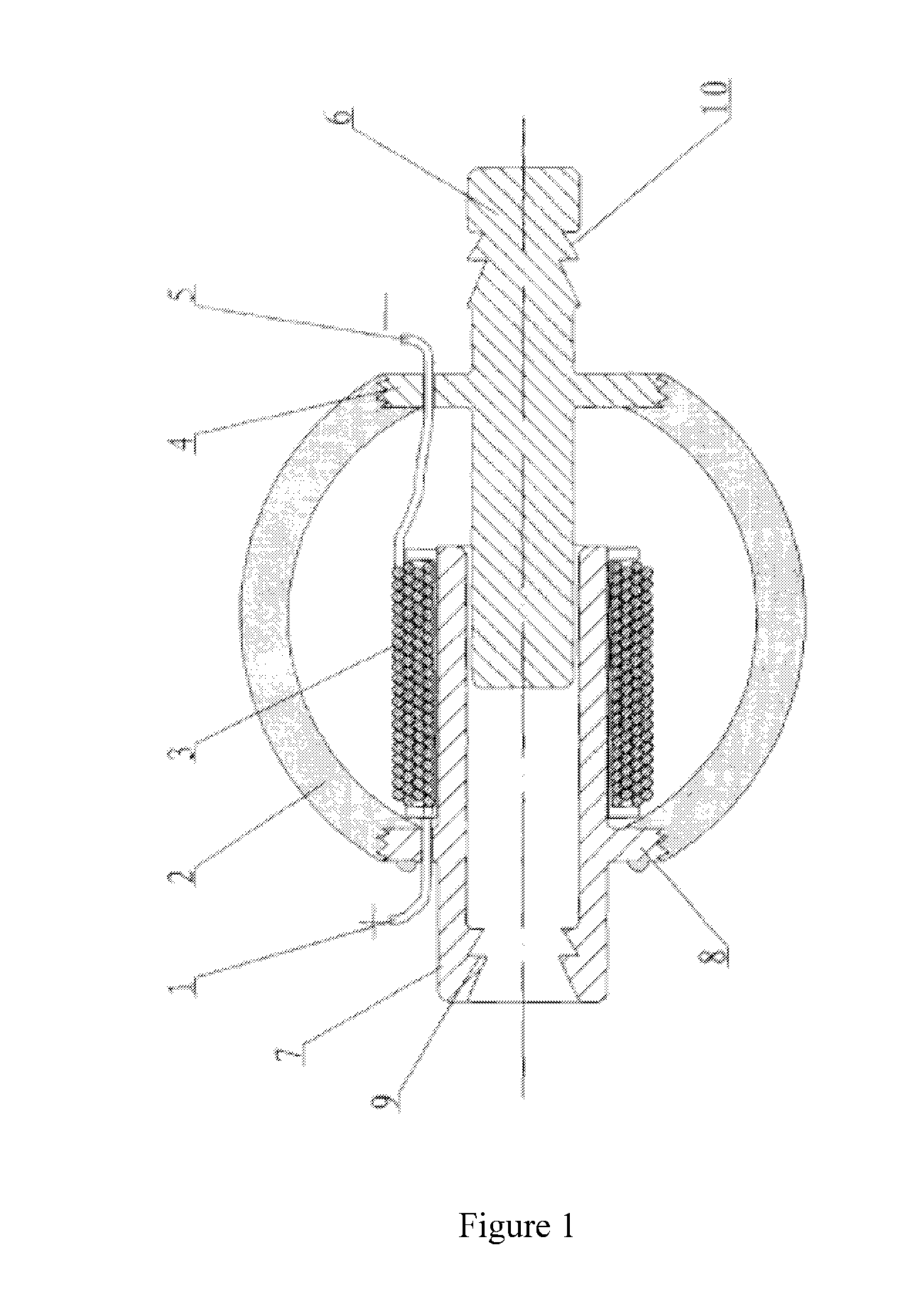
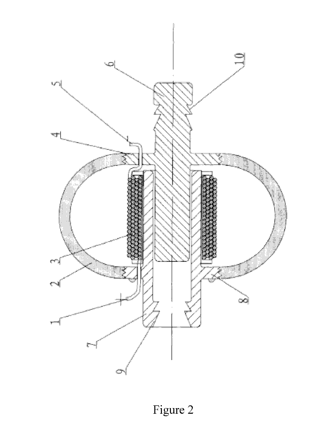
[0012]A bionic telescopic matrix unit is shown in FIG. 1 through FIG. 4. This telescopic matrix unit is composed of a slide shaft (6), a metal guide pipe (7), an elastic telescopic shell (2) and an electromagnetic coil (3). In the elastic telescopic shell (2), the slide shaft (6) made of a permanent magnet extends into the metal guide pipe (7) via the front end of said pipe (7) and comes into sliding contact with the inner tube wall of the metal guide pipe (7). The rear end of the metal guide pipe (7) and the front end of the slide shaft (6) protrude out through the back and front openings of the elastic telescopic shell (2), respectively. Furthermore, the front and back openings of the elastic telescopic shell (2) are secured to the outer wall of the metal slide pipe (7) and the slide shaft (6) to connect said metal guide pipe (7) to said slide shaft (6). The elongation length of the elastic telescopic shell (20 matches the reciprocating stroke of the slide shaf...


PUM


Abstract

A bionic telescopic matrix unit is disclosed, which is composed of a slide shaft (6), a metal guide pipe (7), an elastic telescopic shell (2) and an electromagnetic coil (3). In the elastic telescopic shell (2), the slide shaft (6) made of a permanent magnet extends into the metal guide pipe (7) via the front end of said pipe (7) and comes into sliding contact with the inner tube wall of the metal guide pipe (7). The rear end of the metal guide pipe (7) and the front end of the slide shaft (6) protrude out through the front and back openings respectively of said elastic telescopic shell (2), said front and back openings of said elastic telescopic shell (2) being fixedly connected to the outer peripheral wall of the metal guide pipe (7) and to the slide shaft (6) respectively, thus connecting the metal guide pipe (7) with the slide shaft (6). The elongation length of the elastic telescopic shell (2) corresponds to the reciprocating stroke of the slide shaft (6) in the guide pipe (7); the electromagnetic coil (3) wound on the outer peripheral wall of the metal guide pipe (7) is covered by the elastic telescopic shell (2). Two ends of the electromagnetic coil (3) are duly connected with the positive and negative poles of a power supply. The telescopic matrix unit can simulate the functions of movement caused by animal muscle tissue extension, thus enabling greater flexibility and freedom in the mechanical limb movements of humanoid, etc. robots.

Description

TECHNICAL FIELD[0001]This invention involves applications in MEMS technology, especially a bionic telescopic matrix unit.BACKGROUND TECHNOLOGY[0002]1. Prior Art[0003]Presently, most power mechanisms are mainly driven by electric motors, engines or hydraulic motors. In particular, industrial robots in many factories are driven by electric motors. This limits joint related activities in the mechanical arms of those robots. In addition, existing robotic research is focused on areas such as improving walking balance and control of humanoid robots and quadruped-like mechanisms. The bionic content is rather small. The movement of humanoid robot and other quadruped-like mechanisms is very stiff. Consequently, their flexibility is limited.[0004]2. Description of Invention[0005]The object of this invention is to provide a bionic telescopic matrix unit, which is capable of mimicking the animal movement resulting from stretching and contraction of muscle tissue. It can then be utilized fully i...

Claims


Application Information

Patent Timeline
IPC IPC(8): H01F3/00
CPCB25J9/1075H01F7/1615B25J9/123
Inventor ZHAO, DEZHENG
Owner ZHAO DEZHENG
Learn More