Methods and apparatuses for a small vehicle jack apparatus

a vehicle jack and jack technology, applied in the direction of mobile jacks, lifting devices, manufacturing tools, etc., can solve the problems of unwieldy use of small jacks, jack stands are often wrong sizes, and hydraulic floor jacks do not always provide a single stable support structure, etc., to achieve negligible weight of the apparatus, increase the capacity of the jack, and reduce the weight of the jack

Active Publication Date: 2012-09-13
MOJACK DISTRIBUTORS
View PDF9 Cites 4 Cited by
  • Summary
  • Abstract
  • Description
  • Claims
  • Application Information

AI Technical Summary

Benefits of technology

[0012]A complete apparatus is necessary, where the wheels of the vehicle may be used to elevate the entire end of a vehicle, rather than relying on the frame or other similar contact points available with typical hydraulic jacks for such a vehicle. A means to provide use of a jack with a stationary vehicle is desired, where the supporting structure can be moved into position on a vehicle, without requiring movement of the vehicle onto the jack means itself.
[0027]The jack assembly is portable, in the sense that the support frame defines wheel axles that are defined as outwardly protruding axles, that are positioned immediately above the rearmost ends of the side frame members of the support frame, and project outward laterally to the side above the support frame. Wheels are used, which have a radius that very closely equals the distance from the axle to the ground, when the main frame is on ground level. For maximum support and strength, the wheels do not contact the ground surface, when the jack is in use. However, if the front portion of the frame is elevated, rotating the frame about the axles, the frame is angled upward from the rear toward the front. As the frame is elevated at the front, the wheels remain stationary as to location, and as the frame pivots around the axles, not only the front portion of the frame is elevated off of the ground level, but the rearmost portion of the frame is also slightly elevated, allowing the supporting wheels to remain and the single contact points of the apparatus and the ground. The entire apparatus can be manipulated into position so that the center of gravity passes through the wheel axles, making the weight of the apparatus negligible, with regard to movement from one location to another. Once the apparatus is positioned with the center of gravity over the wheel axles, it can be easily rolled from one point to another by a single person.

Problems solved by technology

The use of hydraulic floor jacks do not always provide a single stable support structure, and jack stands are often the wrong size with regard to the elevation requirements for the small vehicles.
In some situations, the angle of the vehicle necessary to accomplish the desired elevation of one end of the vehicle, makes the use of small jacks unwieldy, since small hydraulic system jacks only have a single contact point.
As the contact point rotates by virtue of the elevation difference between the front and back end of the vehicle, the contact point with the hydraulic jack may become unstable.
Further, the amount of elevation necessary will often exceed a hydraulic jack assembly's capability.

Method used


Image

  • Methods and apparatuses for a small vehicle jack apparatus
  • Methods and apparatuses for a small vehicle jack apparatus
  • Methods and apparatuses for a small vehicle jack apparatus

Examples


Embodiment Construction

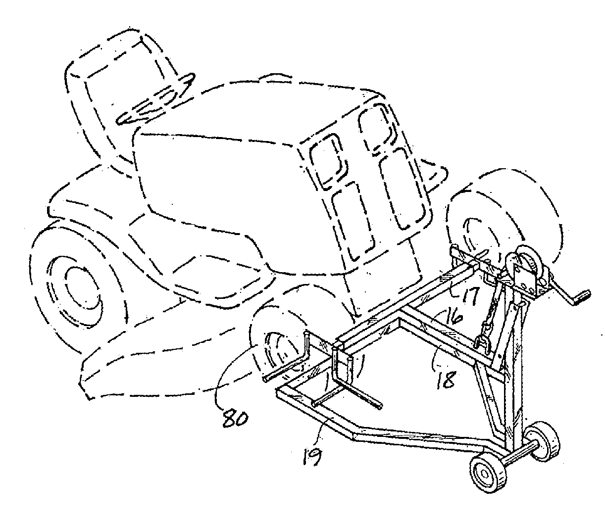
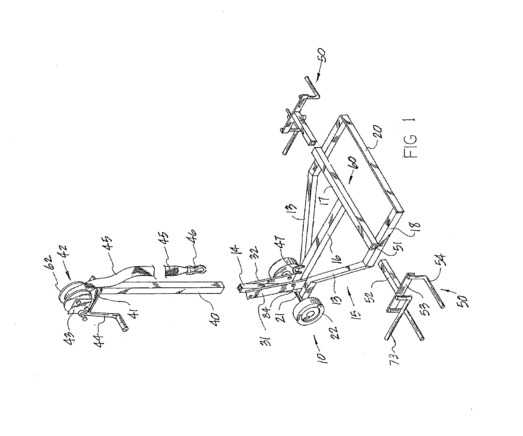
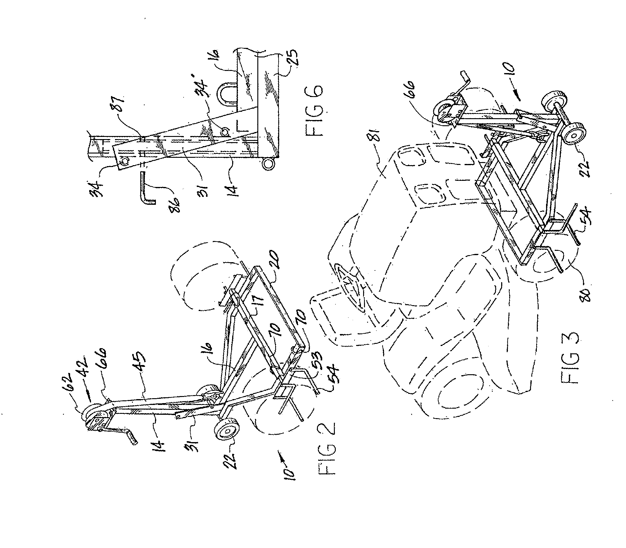
[0041]Referring to FIG. 1, the improved small vehicle jack apparatus 10 is shown. Said apparatus 10 is comprised of a support frame 15, a lifting frame 60, a lifting means 42, and a wheel support means 50. The support frame 15 is comprised of two generally parallel crossbar rest members 18 and 19, which are spaced apart by a front member 20. A further improved configuration is shown also in FIG. 8, in which the support frame 15 is identical with regard to the front portion, where crossbar rest members 18 and 19 are separated by front member 20, but where the rear portion of the crossbar rest members 18 and 19 are not angled, but maintain a generally straight configuration. As FIG. 8 depicts, the support frame 15 may also be defined by cross bar rest members 18 and 19, which are spaced apart by front member 20, and also spaced apart by back support members 71 and 72, to form a rectangular configuration. In either configuration, members 18, 19 and 20, comprise the portion of the suppo...


PUM


Abstract

An apparatus with a wheel engagement mechanism for operation with a jack assembly for engaging and elevating two wheels of a multi-wheeled vehicle relative to the ground is provided. The apparatus includes a base, a support member connected to the base, and a wheel support assembly. The wheel support assembly includes wheel supports connected at the ends of the wheel support that extend outward from the wheel support assembly for supporting two wheels of the vehicle. The apparatus also includes an actuation mechanism for selectively raising and selectively lowering the wheel support assembly to raise and lower the vehicle. A method of assembling the apparatus is also provided.

Description

CROSS-REFERENCE TO RELATED APPLICATIONS[0001]This application claims the benefit of and is a continuation of U.S. application Ser. No. 12 / 252,992, filed Oct. 16, 2008, which is a continuation of U.S. application Ser. No. 11 / 327,264, filed Jan. 7, 2006, which is a Continuation-in-Part of U.S. application Ser. No. 11 / 147,571, filed Jun. 8, 2005, now U.S. Pat. No. 7,823,861, the contents of which are hereby incorporated by reference.BACKGROUND OF THE INVENTION[0002]Numerous small vehicle jacks have been invented to deal with the necessity of raising vehicles smaller than typical automobiles, for purposes of performing repairs and other typical needs. Generally, the jacks have been specific as to what kind of vehicle they were adapted to.[0003]Referring now to U.S. Pat. No. 4,066,243 (Johnson), a jack for the use with automobile bumpers is shown, in which a frame is provided as a support means for a vertical pipe, which has a sleeve, which moves upward and downward around said pipe. A t...

Claims


Application Information

Patent Timeline
Patent Type & Authority Applications(United States)
IPC IPC(8): B66F7/28B23P11/00
CPCB66F7/26Y10T29/49826B66F7/28B66F5/02
Inventor KRUG, NORMAN
Owner MOJACK DISTRIBUTORS
Why Eureka
Try Eureka