
Method and apparatus for radio antenna frequency tuning

a radio antenna and frequency tuning technology, applied in the direction of resonant antennas, receiver monitoring, transmission monitoring, etc., can solve the problems of affecting the performance of antennas, the designer is forced to compromise the performance in some frequency bands, and the antenna cannot radiate efficiently at all frequencies

Active Publication Date: 2012-08-23
NXP USA INC
View PDF4 Cites 126 Cited by
  • Summary
  • Abstract
  • Description
  • Claims
  • Application Information

AI Technical Summary

Benefits of technology

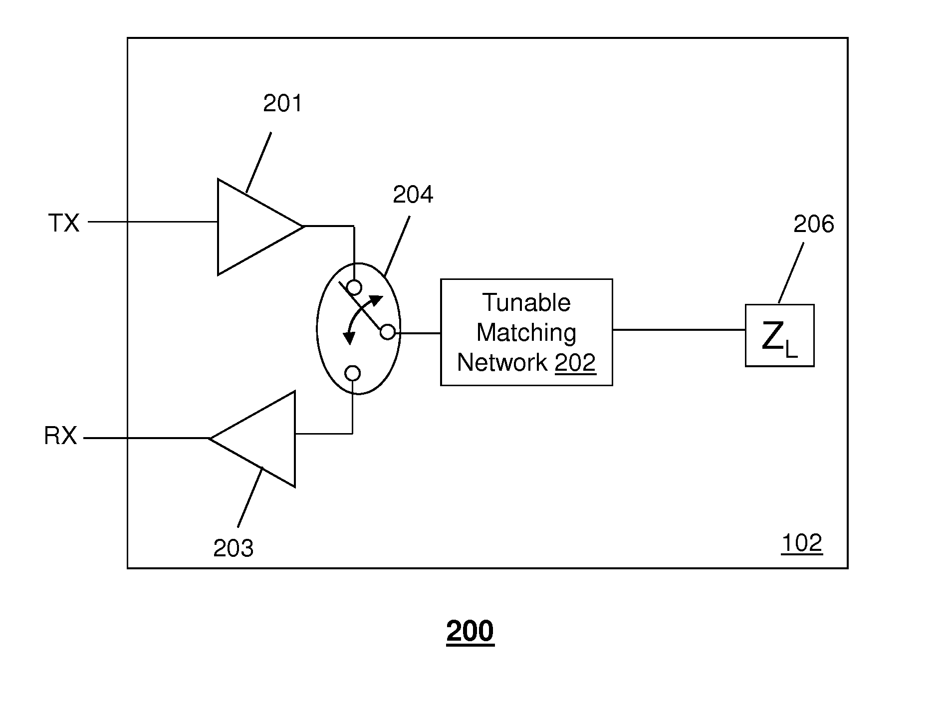
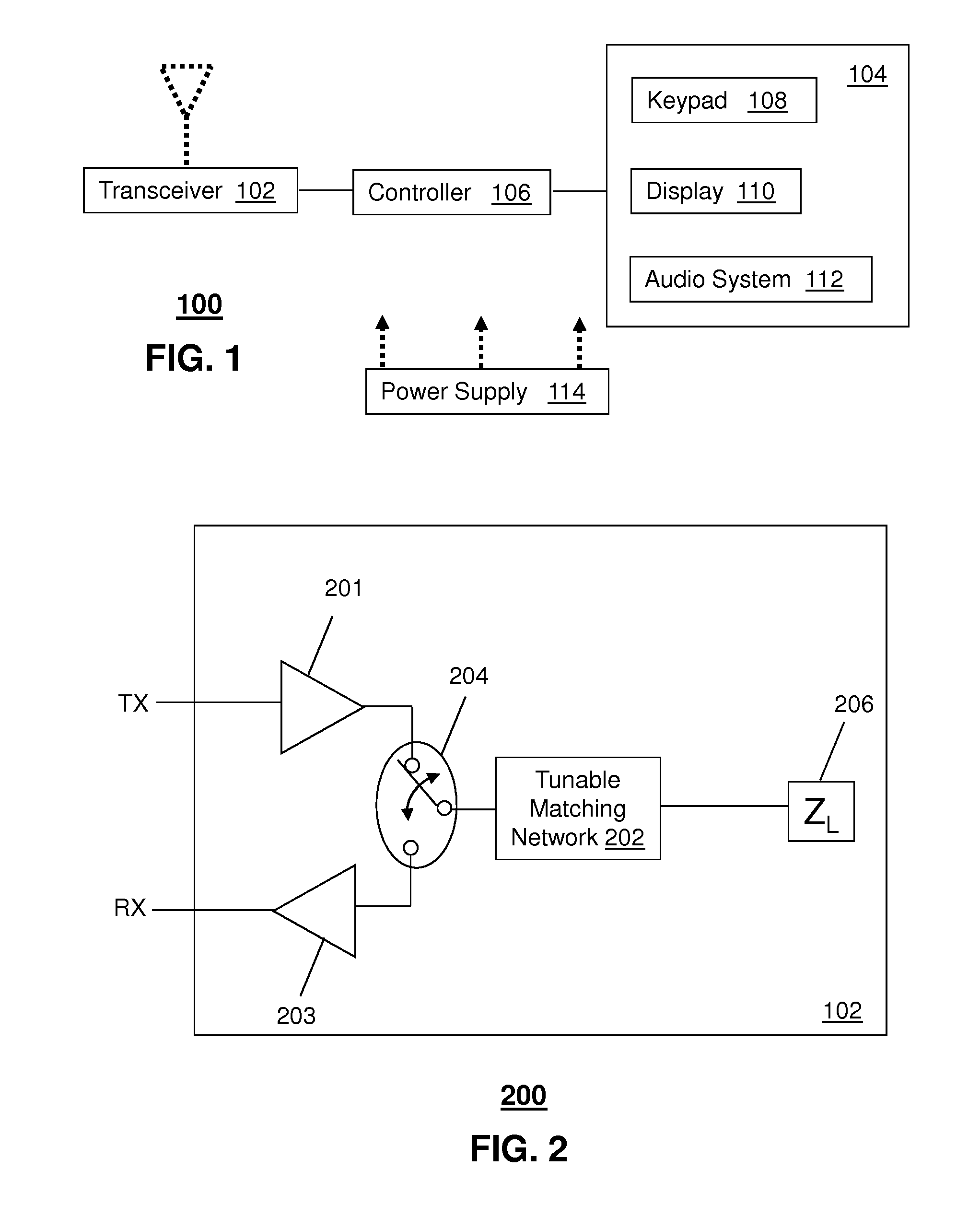
[0015]One embodiment of the present disclosure entails a method to select a tuning state of a tunable matching network operable in a communication device, where the tunable matching network has a tunable reactance that affects one or more performance parameters of the communication device. The method can include performing the selection of the tuning state based on radio frequency and incomplete information about the antenna environment without direct feedback on the performance from the antenna, and identifying the tuning state resulting in the most desirable performance of the communications device.

Problems solved by technology

Due to size constraints, and aesthetic design reasons, the antenna designer is forced to compromise the performance in some of the frequency bands.
The antenna will not radiate efficiently at all frequencies due to the nature of the design, and the power transfer between the antenna, the power amplifier, and the receiver in the radio will vary significantly.
Additionally, an antenna's performance is impacted by its operating environment.
For example, multiple use cases exist for radio handsets, which include such conditions as the placement of the handset's antenna next to a user's head, or in the user's pocket or the covering of an antenna with a hand, all of which can significantly impair the wireless device antenna's radiated efficiency.
Further, many existing radios use a simple circuit composed of fixed value components that are aimed at improving the power transfer from power amplifier to antenna, or from the antenna to the receiver, but since the components used are fixed in value there is always a compromise when attempting to cover multiple frequency bands and multiple use cases.

Method used


Image

  • Method and apparatus for radio antenna frequency tuning
  • Method and apparatus for radio antenna frequency tuning
  • Method and apparatus for radio antenna frequency tuning

Examples


Embodiment Construction

[0013]The present disclosure provides a method and apparatus for radio antenna frequency tuning. One or more exemplary embodiments can employ an open loop mechanism to solve the fundamental problems associated with antenna performance over a range of frequencies and use cases.

[0014]One or more exemplary embodiments can address applying tuning to changing antenna environments without the need for, or use of, a direct feedback loop from the antenna. However, other embodiments can utilized a combination of open loop and closed loop feedback.

[0015]One embodiment of the present disclosure entails a method to select a tuning state of a tunable matching network operable in a communication device, where the tunable matching network has a tunable reactance that affects one or more performance parameters of the communication device. The method can include performing the selection of the tuning state based on radio frequency and incomplete information about the antenna environment without dire...


PUM


Abstract

A system that incorporates teachings of the present disclosure may include, for example, a non-transitory computer-readable storage medium, which can include computer instructions to determine a subset of use cases from a group of use cases stored in a memory of a communication device, and to determine a target use case from among the subset of use cases based on an operational parameter associated with a transceiver of the communication device. Additional embodiments are disclosed.

Description

FIELD OF THE DISCLOSURE[0001]The present disclosure relates to a method and apparatus for radio antenna frequency tuning and in particular determining tuning states in a communication device.BACKGROUND[0002]Existing multi-frequency wireless devices (e.g., radios) use an antenna structure that attempts to radiate at optimum efficiency over the entire frequency range of operation, but can really only do so over a subset of the frequencies. Due to size constraints, and aesthetic design reasons, the antenna designer is forced to compromise the performance in some of the frequency bands. An example of such a wireless device could be a mobile telephone that operates over a range of different frequencies, such as 800 MHz to 2200 MHz. The antenna will not radiate efficiently at all frequencies due to the nature of the design, and the power transfer between the antenna, the power amplifier, and the receiver in the radio will vary significantly.[0003]Additionally, an antenna's performance is ...

Claims


Application Information

Patent Timeline
Patent Type & Authority Applications(United States)
IPC IPC(8): H04B17/00H03H7/40
CPCH01Q1/242H01Q9/14H04B1/18H04B1/401H04B1/0458H03H7/40H04B17/26H04B17/318
Inventor HOIRUP, CARSTENMANSSEN, KEITHGREENE, MATTHEW
Owner NXP USA INC
Learn More