
Scheme for Multi-Cell UL Sounding Transmission

a multi-cell, ul technology, applied in the direction of orthogonal multiplex, site diversity, broadcast service distribution, etc., can solve the problems of increasing the burden on the srs resources, increasing the overhead of comp sounding, and having to deal with problems

Active Publication Date: 2012-08-23
HMD GLOBAL
View PDF9 Cites 37 Cited by
  • Summary
  • Abstract
  • Description
  • Claims
  • Application Information

AI Technical Summary

Benefits of technology

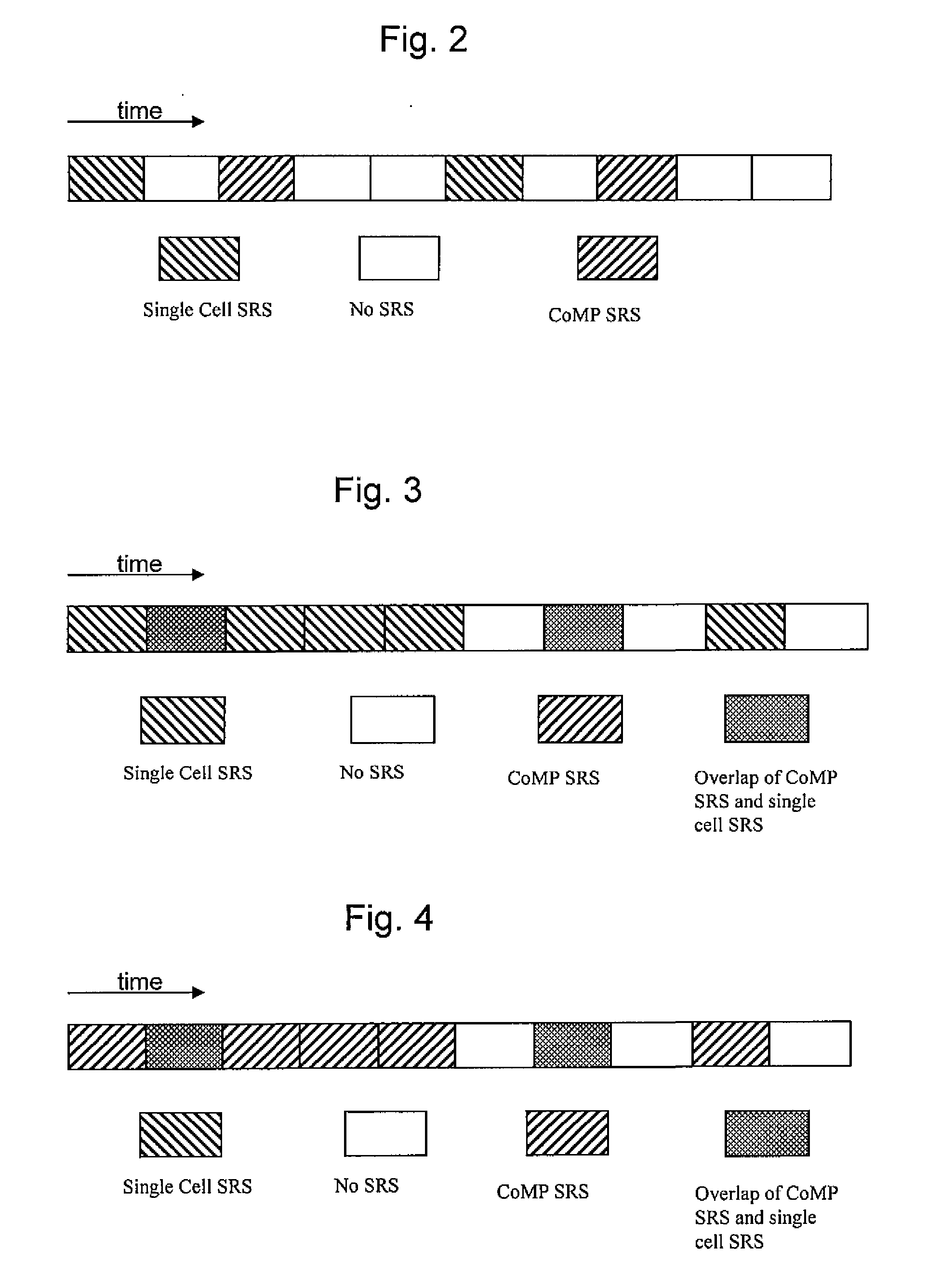
[0018]the predetermined configuration parameters comprise one or more of periodicity and offset in time domain, initial physical resource block, bandwidth and frequency hopping mode in frequency domain.

Problems solved by technology

However, in emerging technologies, there are always also some problems that have to be dealt with.
Getting channel state information from interfering cells, i.e. overlapping cells, by using sound reference signals (SRS) in uplink (UL), however, will increase the load on the SRS resources as the resource has to be reserved in the interfering cell as well.
Thus, there arises the problem of increased overhead with CoMP sounding.

Method used


Image

  • Scheme for Multi-Cell UL Sounding Transmission
  • Scheme for Multi-Cell UL Sounding Transmission
  • Scheme for Multi-Cell UL Sounding Transmission

Examples


Embodiment Construction

[0041]In the following, embodiments of the present invention are described by referring to general and specific examples of the embodiments. It is to be understood, however, that the description is given by way of example only, and that the described embodiments are by no means to be understood as limiting the present invention thereto.

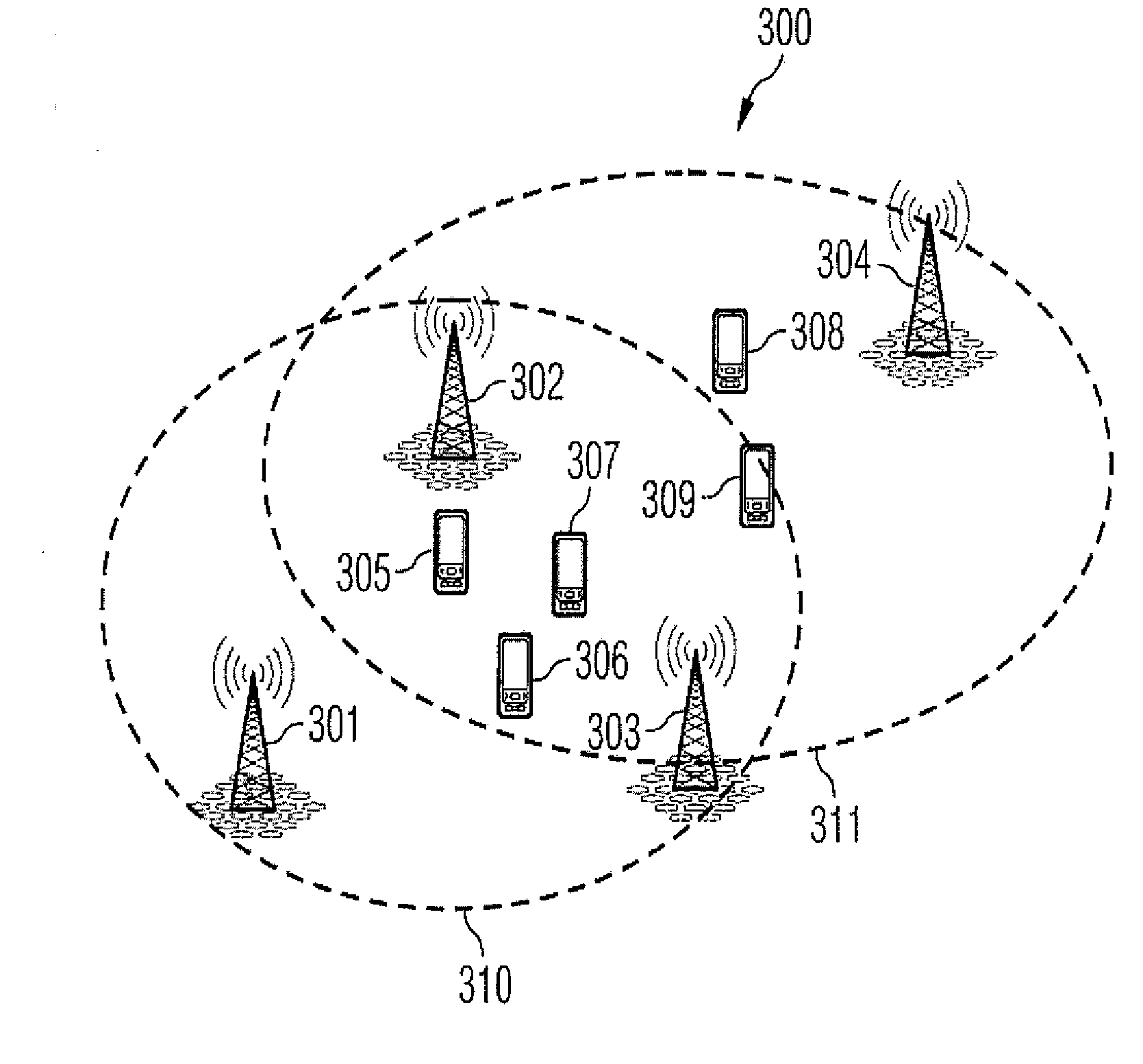
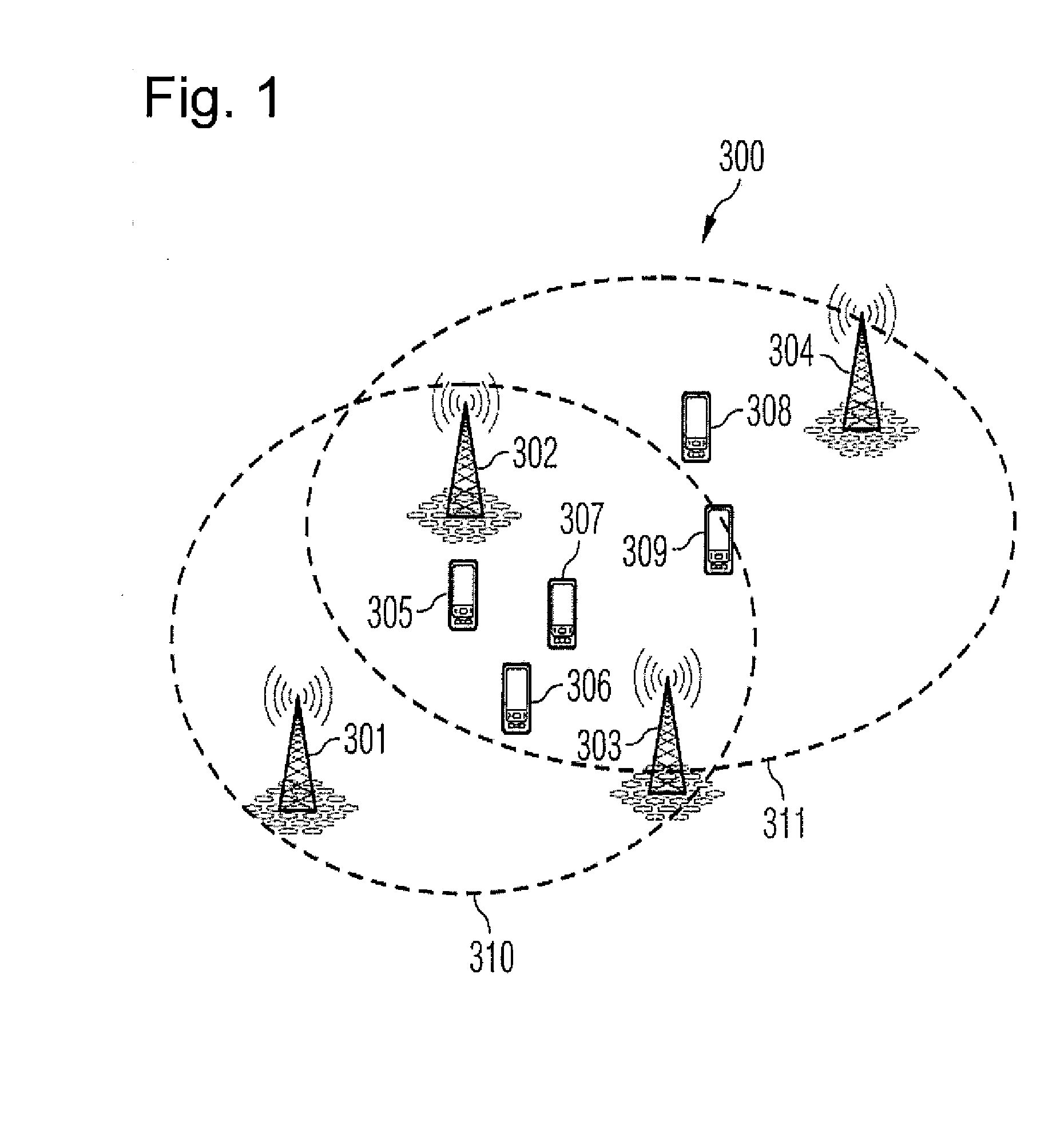
[0042]FIG. 1 shows an example of a communication network to which the present invention is applicable. According to the example shown in FIG. 1, the communication network is a cellular mobile communication network.

[0043]The communication network 300 comprises two CoMP sets 310 and 311 each comprising corresponding base stations 301, 302, 303 and 302, 303, 304, respectively. A CoMP set refers to an UE specific set of base stations from which the UE is receiving / transmitting jointly. Furthermore, a plurality of network elements 305, 306, 307, 308 and 309 are schematically depicted in FIG. 1. However, the communication network may of course comprise a mu...


PUM


Abstract

The present invention provides a method, respective apparatuses, system and computer program product for obtaining channel state information in a coordinated multi-point transmission / reception communication network. The method includes allocating a first sounding resource to at least one of a plurality of user equipment in a coordinated multi-point transmission / reception communication network for transmitting sounding reference signal to a base station of a serving cell, and allocating a second sounding resource to the at least one user equipment for transmitting sounding reference signal to a base station of an interfering cell, wherein the first and the second sounding resource are different from each other.

Description

[0001]Scheme for multi-cell UL sounding transmission for obtaining channel state information in a coordinated multipoint transmission / receiving communication network.FIELD OF THE INVENTION[0002]The present invention relates to the field of obtaining channel state information in a coordinated multipoint transmission / receiving communication network, and more particularly, in a mobile communication network like a Long Term Evolution advanced (LTE-A) communication network. Additionally, the invention relates to apparatuses in a communication network, like e.g. a base station, and more particularly, to a (enhanced) node B in a LTE-A communication network and user equipment. Moreover, the invention relates to a program code and a computer readable medium carrying the program code.BACKGROUND[0003]The coordinated multipoint transmission and reception (CoMP) concept is an emerging technology in communication networks. However, in emerging technologies, there are always also some problems tha...

Claims


Application Information

Patent Timeline
Patent Type & Authority Applications(United States)
IPC IPC(8): H04W72/04H04W4/06
CPCH04J11/0053H04L5/0035H04L5/0078H04L5/0048H04W72/541H04B7/024
Inventor LIU, JING XIUSKOV, PETER
Owner HMD GLOBAL
Learn More