
Method and apparatus to detect transponder tagged objects, for example during medical procedures

a technology of transponder and object, applied in the field of detection of the presence or absence of objects tagged with transponders, can solve the problems of inefficient manual approach, serious adverse medical consequences, additional surgery, etc., and achieve the effect of increasing the sample averaging tim

Active Publication Date: 2012-08-23
TYCO HEALTHCARE GRP LP
View PDF14 Cites 9 Cited by
  • Summary
  • Abstract
  • Description
  • Claims
  • Application Information

AI Technical Summary

Benefits of technology

[0013]The control system may be further configured to compare at least one noise level measured from before a first interrogation portion of the cycle a noise level measured after the first interrogation portion of the cycle; and increase the sample averaging time for sampling responses to interrogation signals if a result of the comparison indicates a variation in excess of a variation threshold.

Problems solved by technology

When used in surgery, failure to locate an object before closing the patient may require additional surgery, and in some instances may have serious adverse medical consequences.
In other medical procedures, such as vaginal child birth deliveries, failure to remove objects, for instance gauze or absorbent pads can lead to infections.
Such a manual approach is inefficient, requiring the time of highly trained personnel, and is prone to error.
However, inexpensive transponders typically have a relatively large variation in the frequency of signals they emit, making it difficult to accurately detect the signals returned by the transponders.
This may be particularly difficult in some environments which are noisy with respect to the particular resonant frequencies of the transponders.
Rooms in hospitals in which medical procedures are performed tend to have increasingly larger amounts of electronic equipment, and hence are becoming notoriously noisy environments.

Method used


Image

  • Method and apparatus to detect transponder tagged objects, for example during medical procedures
  • Method and apparatus to detect transponder tagged objects, for example during medical procedures
  • Method and apparatus to detect transponder tagged objects, for example during medical procedures

Examples


Embodiment Construction

[0091]In the following description, certain specific details are set forth in order to provide a thorough understanding of various disclosed embodiments. However, one skilled in the relevant art will recognize that embodiments may be practiced without one or more of these specific details, or with other methods, components, materials, etc. In other instances, well-known structures associated with transmitters, receivers, or transceivers and / or medical equipment and medical facilities have not been shown or described in detail to avoid unnecessarily obscuring descriptions of the embodiments.

[0092]Unless the context requires otherwise, throughout the specification and claims which follow, the word “comprise” and variations thereof, such as, “comprises” and “comprising” are to be construed in an open, inclusive sense, that is as “including, but not limited to.”

[0093]Reference throughout this specification to “one embodiment” or “an embodiment” means that a particular feature, structure...


PUM


Abstract

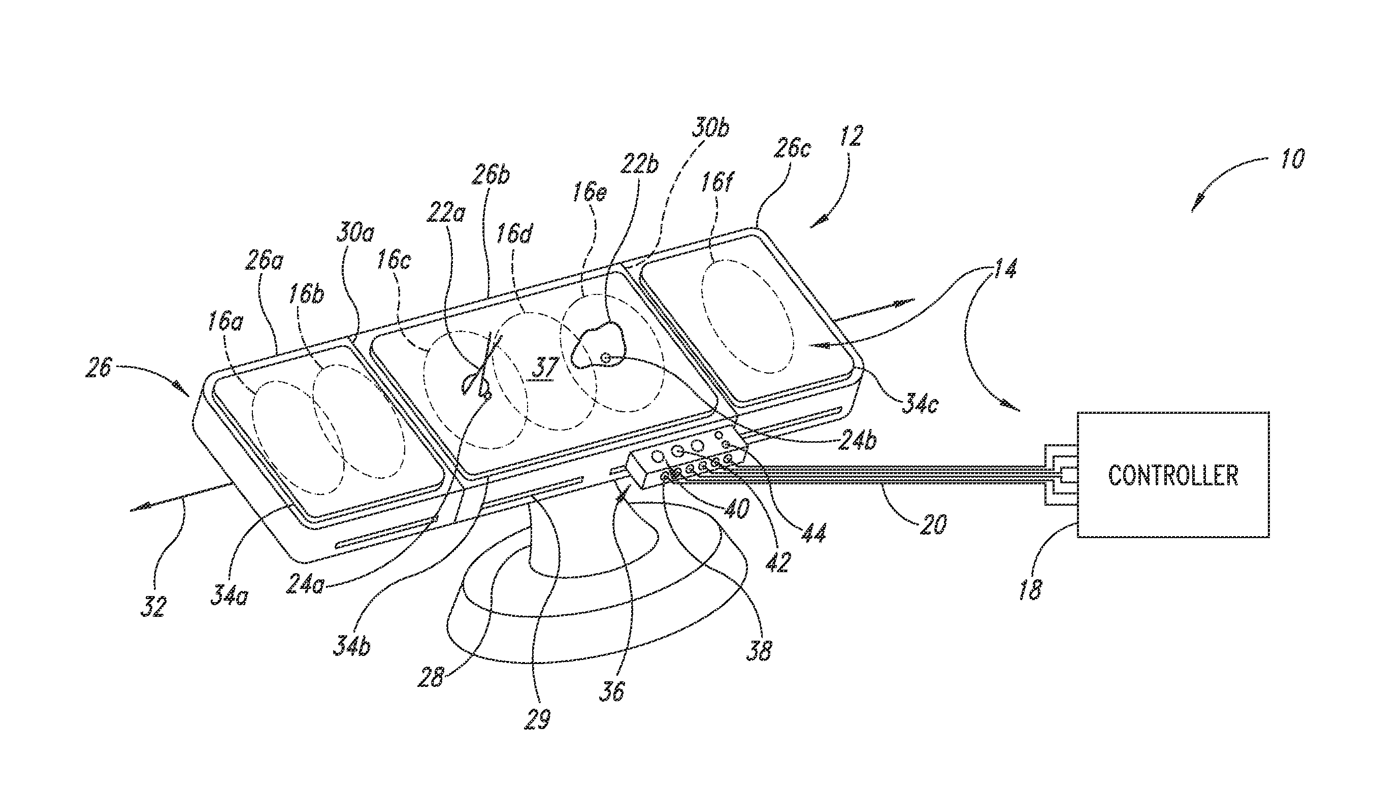
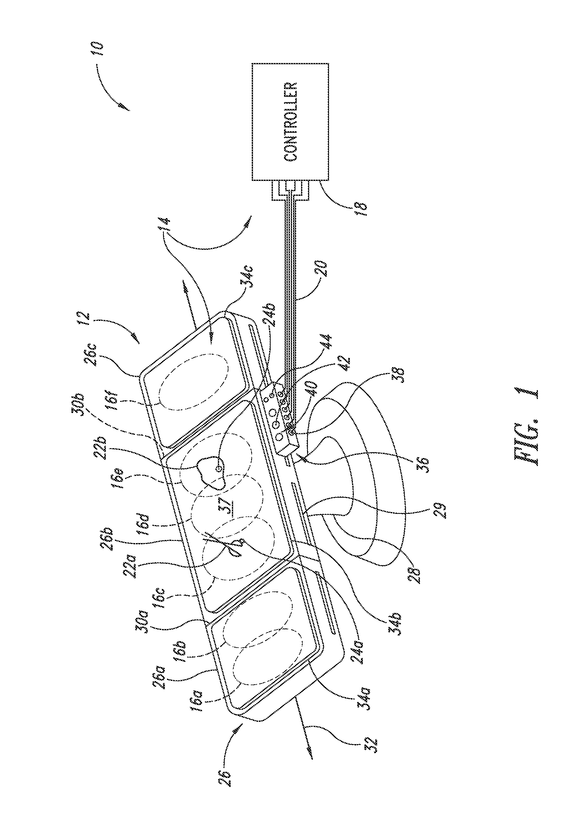
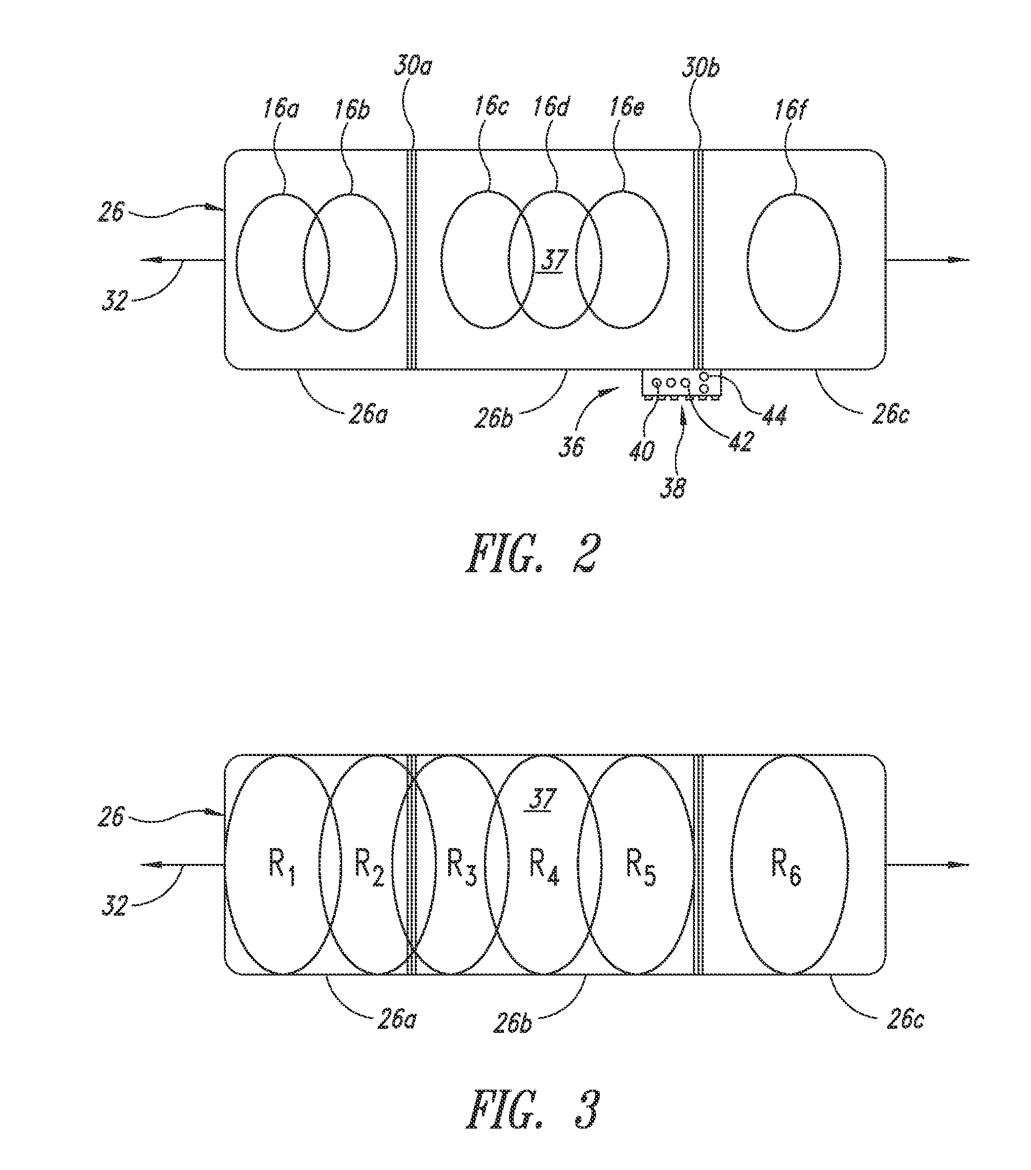
The presence or absence of objects (e.g., medical implements, medical supplies) tagged with transponders may be determined in an environment in which medical procedures (e.g., surgery) are performed via an interrogation and detection system which includes a controller and a plurality of antennas positioned along a patient support structure. The antennas may, for example, be positioned along an operating table, bed, a mattress or pad or a sheet and may be radiolucent. Respective antennas may successively be activated to transmit interrogation signals. Multiple antennas may be monitored for responses from transponders to the interrogation signals. For example, all antennas other than the antenna that transmitted the most recent interrogation signal may be monitored.

Description

CROSS REFERENCE TO RELATED APPLICATIONS[0001]This application is a divisional of U.S. patent application Ser. No. 12 / 606,688 filed Oct. 27, 2009, now pending, which claims benefit under 35 U.S.C. 119(e) to U.S. provisional patent application Ser. No. 61 / 109,104 filed Oct. 28, 2008; U.S. provisional patent application Ser. No. 61 / 222,443 filed Jul. 1, 2009; and U.S. provisional patent application Ser. No. 61 / 242,704 filed Sep. 15, 2009, all of which are incorporated herein by reference in their entireties.BACKGROUND[0002]1. Technical Field[0003]This disclosure generally relates to the detection of the presence or absence of objects tagged with transponders, which may, for example, allow the detection of medical supplies, for instance surgical objects during surgery.[0004]2. Description of the Related Art[0005]It is often useful or important to be able to determine the presence or absence of an object.[0006]For example, it is important to determine whether objects associated with a me...

Claims


Application Information

Patent Timeline
Patent Type & Authority Applications(United States)
IPC IPC(8): H04Q5/22H01Q21/00
CPCA61B19/44A61B2019/448A61G13/10A61G13/1265A61G13/127H01Q7/00G06K7/10079G06K7/10128H01Q21/00H01Q5/00G06K7/0008A61B90/90A61B90/98
Inventor BLAIR, WILLIAM A.BARNES, BRUCE E.POIRIER, DAVID A.
Owner TYCO HEALTHCARE GRP LP
Learn More