
Artificial Lift Modeling Methods and Systems

Inactive Publication Date: 2012-08-23
TROSHKO ANDREY A +1
View PDF20 Cites 23 Cited by
  • Summary
  • Abstract
  • Description
  • Claims
  • Application Information

AI Technical Summary

Benefits of technology

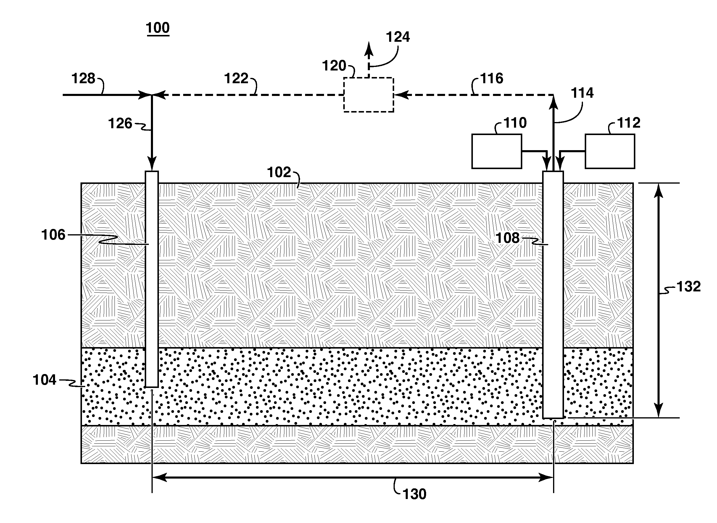
[0015]In a fourth embodiment of the present disclosure, a control system is provided. The control system includes a reservoir data set comprising at least a pressure boundary condition of a subterranean formation and an in-situ solids concentration of a dense slurry near an inlet of a producer pipe of an artificial lift system, the artificial lift system comprising: a) a well bore containing a producer pipe extending through an overburden below a surface of the earth into an oil sand reservoir, the producer pipe having an opening configured to permit the flow of a dense slurry into the producer pipe from the oil sand reservoir; b) a jet pump incorporated into the well bore configured to inject a power fluid at

Problems solved by technology

Other methods breakup the sand matrix in which the heavy oil is entrained by water injection to produce the formation sand with the oil; however, the recovery of bitumen using water injection techniques is limited to the area proximal the bore hole.
These methods generally have low recovery ratios and are expensive to operate and maintain.
Efficiently and effectively recovering these resources for use in the market is one of the world's toughest energy challenges.
In cases of CSS and SAGD, sand production is not desirable.

Method used


Image

  • Artificial Lift Modeling Methods and Systems
  • Artificial Lift Modeling Methods and Systems
  • Artificial Lift Modeling Methods and Systems

Examples


examples

[0093]The processes, models, and systems described above can be used for a variety of purposes, including designing a slurry lift system. In one aspect, the numerical model can predict producer well performance for various physical parameters such as depth of the producer pipe inlet h, a flow rate of the jet pump, horizontal pressure gradient (∂p / ∂r), in situ slurry concentration cin, a configuration of the jet pump, a distance between an injection well and the producer pipe inlet, an inner diameter of the producer pipe, a flow rate of the fluid lift apparatus, a configuration of the fluid lift apparatus, and combinations of these and other physical parameters.

[0094]For this example, it is helpful to refer to FIGS. 4A-4B. In particular, the horizontal pressure gradient (∂p / ∂d) was set by specifying a pressure of zero at the outlet of the producer pipe 414 and setting the vertical inlet pressure profile 412 as:

pin(x)≅R∂p∂r+cinΔρgx(18)

[0095]In this example, the incoming slurry concent...


PUM


Abstract

Methods for modeling, configuring, and controlling artificial lift processes are provided as well as systems for controlling artificial lift and hydrocarbon production systems. In particular, the methods and systems include the use of computation solid-liquid slurry models and reservoir inputs configured to provide inputs to configure parameters of an artificial lift system. The methods and systems may also incorporate fluid lift computational models and volume of fluid (VOF) models for verifying the numerical results. The disclosed methods and systems may beneficially be used in combination with hydrocarbon production processes such as fluidized in-situ reservoir extraction (FIRE) process; a SRBR process; an enhanced CHOPS process; and any combination thereof.

Description

CROSS-REFERENCE TO RELATED APPLICATION[0001]This application claims the benefit of U.S. Provisional Patent Application 61 / 238,569 filed 31 Aug. 2009 entitled ARTIFICIAL LIFT MODELING METHODS AND SYSTEMS, the entirety of which is incorporated by reference herein.FIELD[0002]Embodiments of the invention relate to methods of modeling artificial lift from a subsurface formation. More particularly, embodiments of the invention relate to methods and systems for modeling artificial lift systems using numerical analysis to more accurately predict reservoir behavior during production and injection of sand and fluids in a hydrocarbon recovery process.BACKGROUND[0003]This section is intended to introduce various aspects of the art, which may be associated with exemplary embodiments of the present invention. This discussion is believed to assist in providing a framework to facilitate a better understanding of particular aspects of the present invention. Accordingly, it should be understood that ...

Claims


Application Information

Patent Timeline
IPC IPC(8): E21B43/12G06F7/60E21B43/16G06F17/10
CPCE21B43/124
Inventor TROSHKO, ANDREY A.YALE, DAVID P.
Owner TROSHKO ANDREY A
Learn More