Method for displacement of water from a porous and permeable formation

Inactive Publication Date: 2012-08-16
CENOVUS ENERGY
View PDF18 Cites 9 Cited by
  • Summary
  • Abstract
  • Description
  • Claims
  • Application Information

AI Technical Summary

Benefits of technology

[0009]In another embodiment, the method further comprises the step of controlling fluid injection into the barrier wells and from the production well to maintain the hydraulic pressure at the gas-confining barrier in excess of the hydraulic pressure within the target region, thereby limiting escape of gas from the target region.
[0010]In another embodiment, the method further comprises the step of monitoring gas production from the production well. The rate of water production from the production well may be controlled to reduce gas production from the production well.
[0033]In an embodiment, the method further comprises the step of controlling fluid injection into the barrier wells and from the production well to maintain the hydraulic pressure barrier in excess of the hydraulic pressure within the target region, thereby limiting escape of gas from the target region.

Problems solved by technology

However, producing such water is a challenge, particularly when the porous and permeable reservoir is very large, and when the water is in hydraulic contact with other resources.
In such situations, application of in situ recovery techniques to harvest the underlying bitumen may be less economically feasible in the presence of such overlying water.
Notably, when a water zone or aquifer is in hydraulic contact with an oil sand, the efficiency of any in situ recovery operation aimed at harvesting petroleum from the underlying oil sand could be seriously compromised.
Thus, irrespective of the quality of the water, the hydraulic contact of the oilsand formation with significant amounts of overlying water is likely to be prejudicial either to conservation of the potable water resource and / or to operational efficiency if the petroleum resource is to be extracted.

Method used


Image

  • Method for displacement of water from a porous and permeable formation
  • Method for displacement of water from a porous and permeable formation
  • Method for displacement of water from a porous and permeable formation

Examples


examples

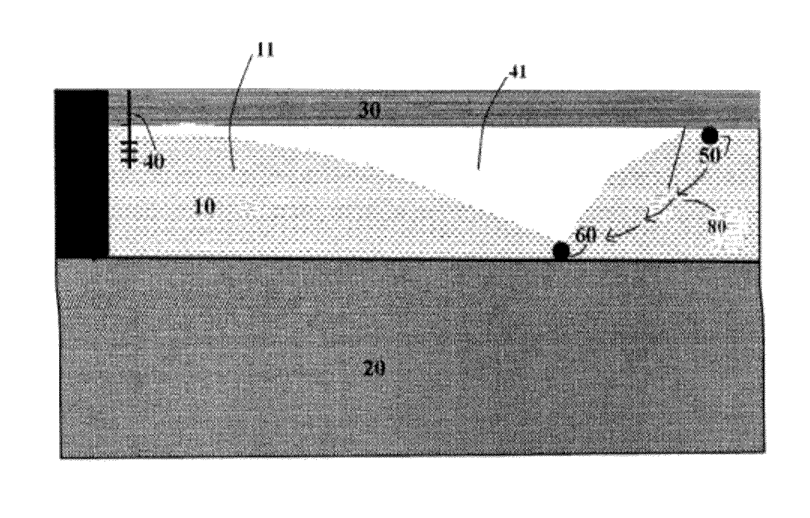
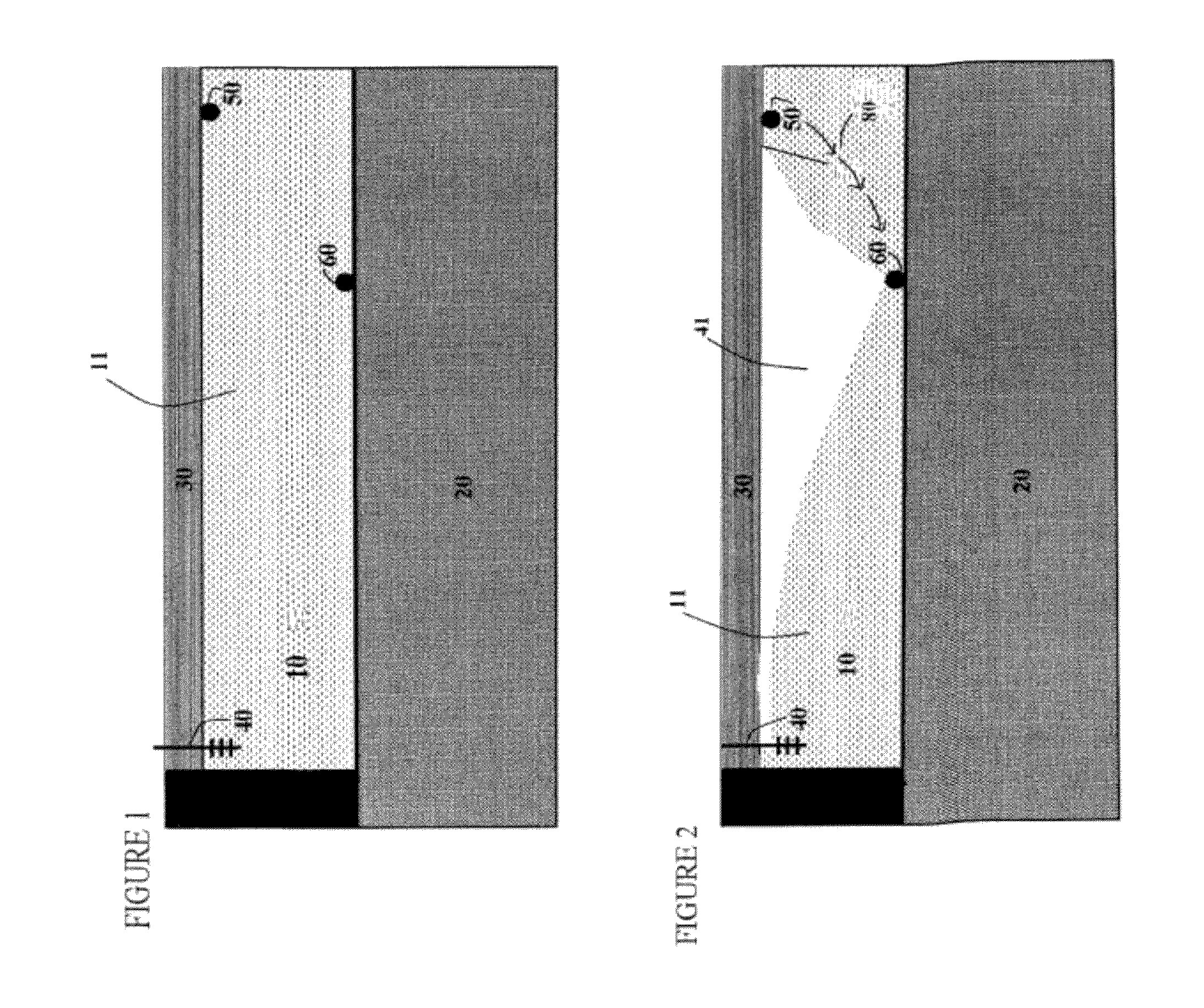
[0092]With reference to FIGS. 5 and 6, simulation results are shown in half-element form. The model accounts for two-phase immiscible flow in a porous medium, including viscosity and density differences between the gas and the water.

[0093]FIG. 5 illustrates the model set-up. For simplicity of illustration, by using a half-element representation, hydraulic confinement is carried out in only one direction, and a single horizontal water injection well positioned to create this hydraulic confinement or barrier is depicted. Gas injection occurs at the near face of the model, and water production at or near the base of the target region is effected using, in this illustration, two water production wells 60. In accordance with the teaching described above, the water production wells 60 are situated so that they are located within the boundaries of the target region, as defined by the imposed hydraulic barrier created through operation of the water injection well. To create this hydraulic b...


PUM


Abstract

A method and system for displacing water from a porous geological formation are provided. The zone to be displaced is defined by the injection of water into one or more barrier wells around the zone. One or more gas injection wells and water production wells are located within the zone. During pressurized gas injection within the zone, the barrier wells are operated to achieve a hydraulic pressure barrier surrounding the zone that is sufficient to prevent penetration therethrough by the injected gas. The well system is operated to concurrently limit gas entry into the water production well. Accordingly, the gas displaces water downward within the zone such that water is produced at the water production wells.

Description

RELATED APPLICATION DATA[0001]This application claims the benefit of and priority of U.S. Provisional Application No. 61 / 441,970 filed Feb. 11, 2011, entitled “Method for Displacement of Water from a Porous Formation” and Canadian Application No. ______ filed May 11, 2011.FIELD OF THE INVENTION[0002]The present invention relates generally to the displacement of water from a porous and permeable formation. More particularly, the present invention relates to a method for isolating a displacement zone within a porous and permeable formation, and then replacing water in the isolated zone with a non-condensing gas.BACKGROUND OF THE INVENTION[0003]Many commercial operations require access to underground reservoirs, including mining operations, oil and gas production, natural gas storage, compressed air energy storage, and carbon dioxide sequestration. In some cases, gaining access to such reservoirs would require the production of water from formations within or around the reservoir. Howe...

Claims


Application Information

Patent Timeline
IPC IPC(8): E21B43/30E21B43/12
CPCE21B43/166G01V9/02E03B3/12E21B43/20Y02A20/00
Inventor CHHINA, HARBIRGITTINS, SIMONSTAVROPOULOS, KATHERINELIU, XIAOHUANWINESTOCK, ALVIN
Owner CENOVUS ENERGY
Why Eureka
Try Eureka