Method and system for reducing emissions from evaporative emissions
a technology of evaporative emissions and emissions reduction, applied in the direction of machines/engines, separation processes, transportation and packaging, etc., can solve the problems of reducing the availability of purge air, reducing the ability to handle large hydrocarbons loads for carbon canister regeneration, and affecting the operation of the carbon canister. the effect of reducing hydrocarbon emissions
Active Publication Date: 2012-08-16
INGEVITY SOUTH CAROLINA
View PDF9 Cites 32 Cited by
- Summary
- Abstract
- Description
- Claims
- Application Information
AI Technical Summary
Benefits of technology
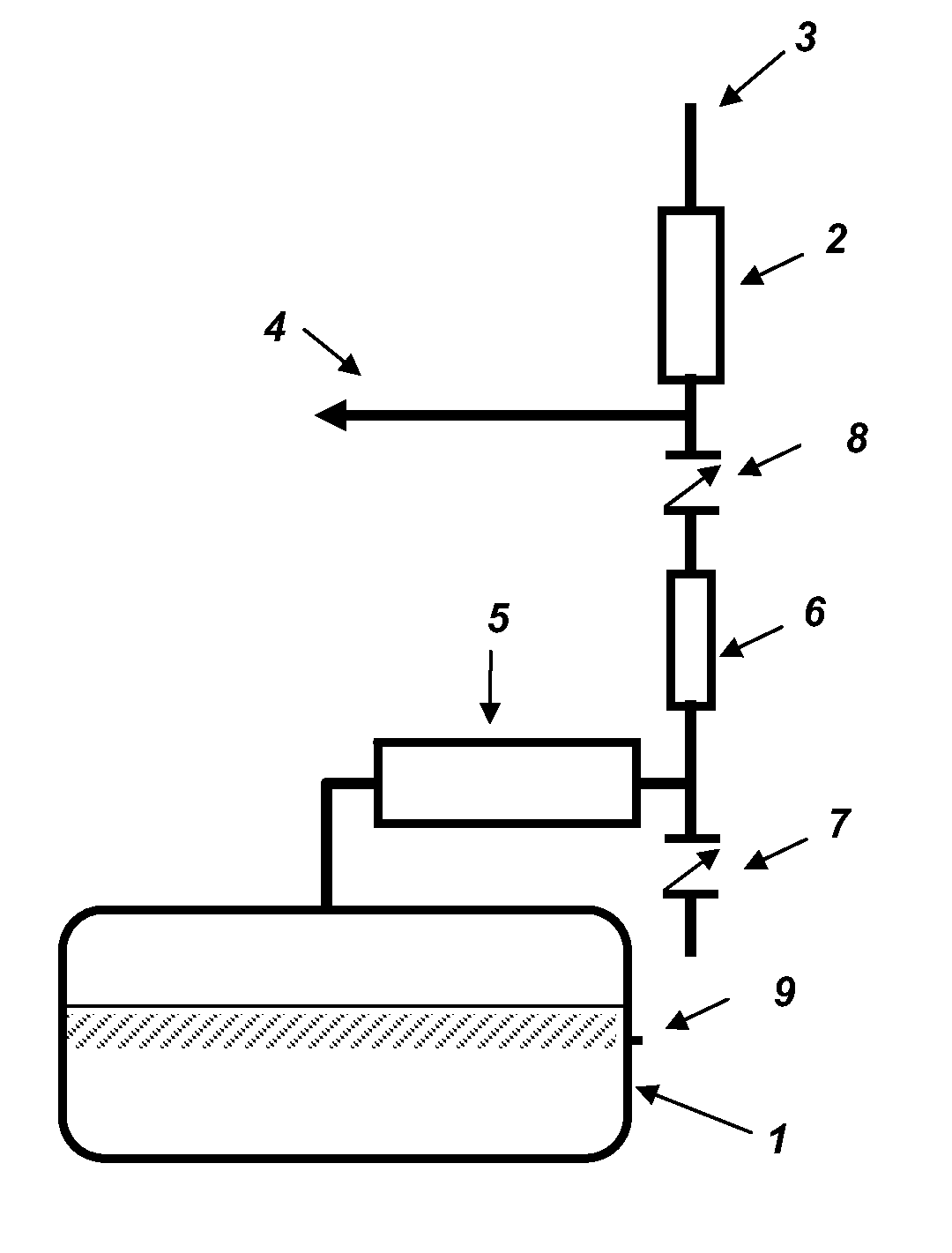
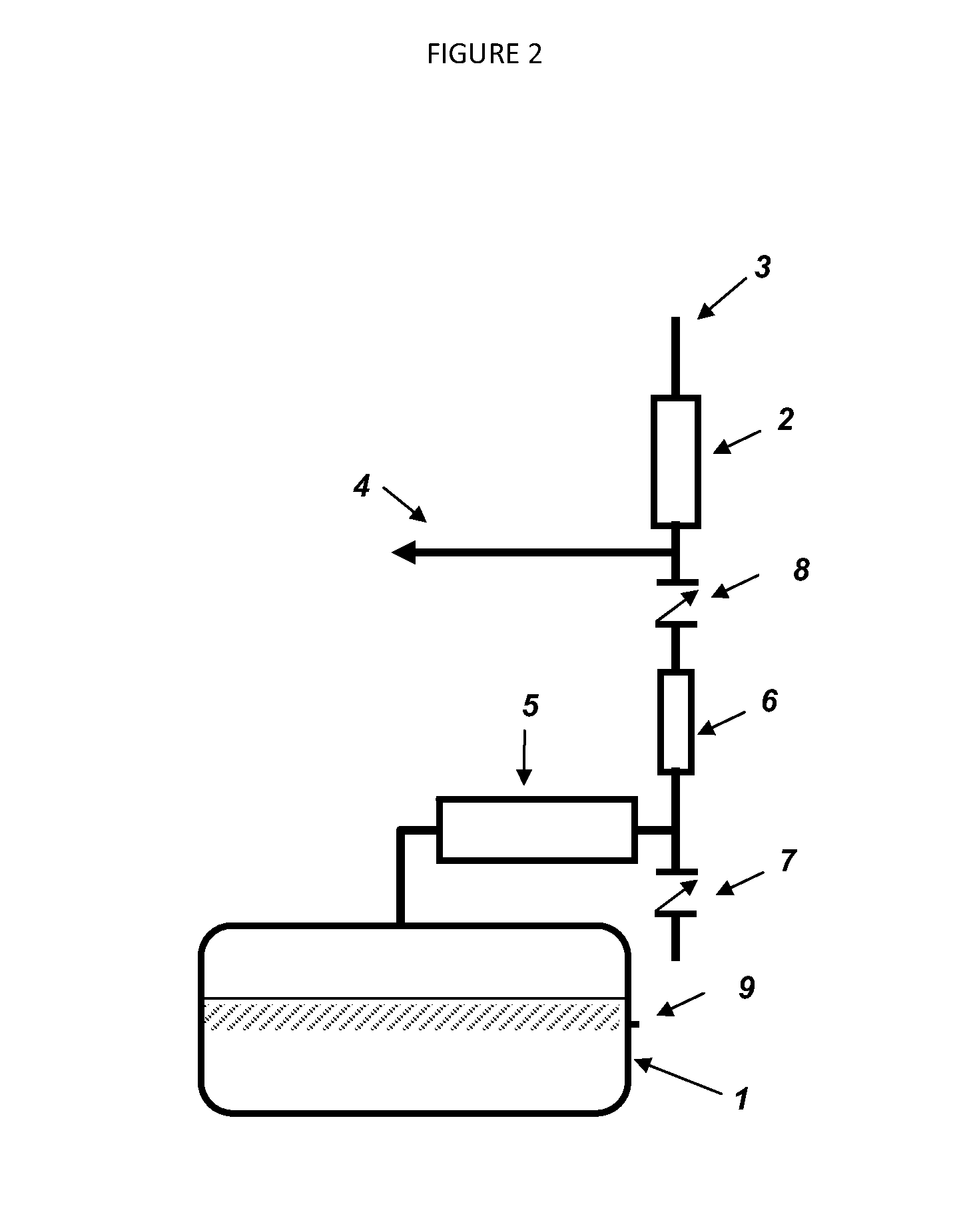
[0012]A method for reducing hydrocarbon emissions from automotive evaporative emissions control systems is disclosed comprising steps of: (1) contacting a vented fuel vapor stream from a fuel tank with a first passive purge canister bed, the passive purge canister bed comprising a vapor adsorbent material and having a passive purge vapor inlet and a passive purge vapor outlet for vapor stream flow; (2) contacting the vapor stream from the passive purge vapor outlet with an active purge canister bed, the active purge canister bed comprising a vapor adsorbent mater
Problems solved by technology
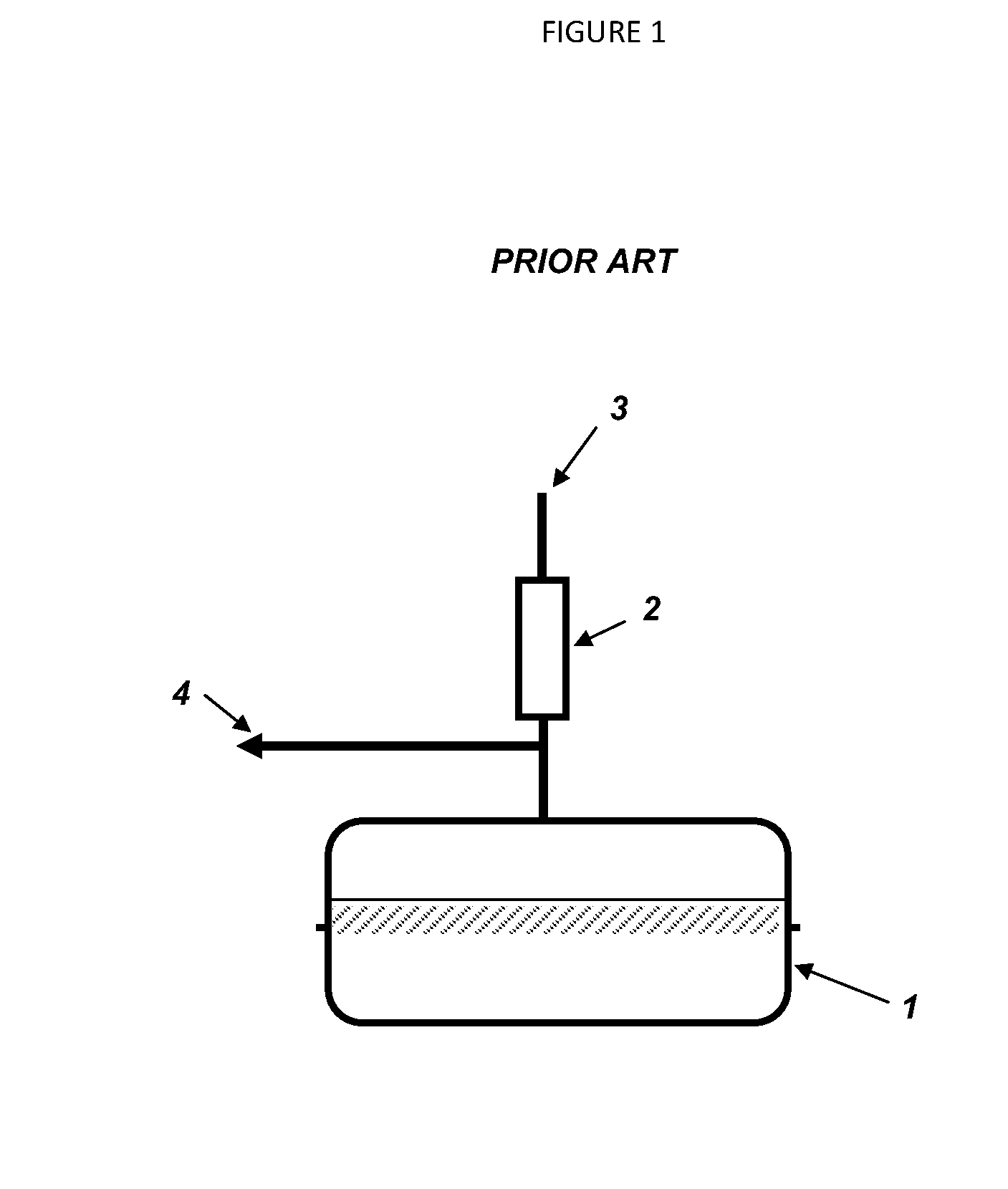
Evaporation of gasoline from motor vehicle fuel systems is a major potential source of hydrocarbon air pollution.
When a carbon canister is placed in the tank vent, the air drawn into the tank during periods of ambient temperature drops is able to provide limited regeneration of the canister.
New engine technologies (such as g
Method used
View moreImage
Smart ImageViewing Examples
Examples
 PUM
 Abstract
A method for reducing hydrocarbon emissions from automotive evaporative emissions control systems comprising steps of: contacting a vented fuel vapor stream from a fuel tank (1) with a first passive purge canister bed (5), the passive purge canister bed comprising a vapor adsorbent material and including a passive purge vapor inlet and a passive purge vapor outlet for vapor stream flow, -contacting a vapor stream from the passive purge vapor outlet with an active purge canister bed, the active purge canister bed (2) comprising a vapor adsorbent material; contacting the active purge canister bed with mechanically convected purge air, wherein the mechanically convected purge air is prevented from flowing through the passive purge canister bed; and contacting the passive purge canister bed with fresh purge air drawn passively by the fuel tank through the passive purge vapor outlet without first contacting said active purge canister bed.
Description
FIELD OF THE DISCLOSURE[0001]This disclosure relates to a method for reducing evaporative hydrocarbon emissions from automotive fuel storage systems that include activated carbon-filled canisters and / or adsorptive monolith-containing canisters wherein the monoliths include activated carbon, as well as to a use of such adsorbing canisters to remove volatile organic compounds and other chemical agents from fluid streams. The disclosure further relates to particular method and system employing passive and active purge canisters and / or canister bed sections for emission control. Moreover, this disclosure relates to decreasing the total mass of hydrocarbons that must be purged and consumed by the engine to fully regenerate the canister.BACKGROUND OF THE DISCLOSURE[0002]Evaporation of gasoline from motor vehicle fuel systems is a major potential source of hydrocarbon air pollution. The automotive industry is challenged to design engine components and systems to contain, as much as possibl...
Claims
Login to View More Application Information
Patent Timeline
 IPC IPC(8): B01D53/02
CPCB60K15/03504B60K2015/03514F02M2025/0881F02M25/089F02M25/0854
Inventor TSCHANTZ, MICHAEL F.MCCRAE, PETER D.
Owner INGEVITY SOUTH CAROLINA
Features
- R&D
- Intellectual Property
- Life Sciences
- Materials
- Tech Scout
- Unparalleled Data Quality
- Higher Quality Content
- 60% Fewer Hallucinations
Learn More Browse by: Latest US Patents, China's latest patents, Technical Efficacy Thesaurus, Application Domain, Technology Topic, Popular Technical Reports.
© 2025 PatSnap. All rights reserved.Legal|Privacy policy|Modern Slavery Act Transparency Statement|Sitemap|About US| Contact US: help@patsnap.com


