
Optical absorption meter

a technology of optical absorption and optical absorption meter, which is applied in the field of optical absorption calorimetry, can solve the problems of affecting the absorption efficiency of optical absorption, so as to improve the absorption sensitivity, reduce the sample heat capacity, and improve the effect of absorption sensitivity

Inactive Publication Date: 2012-08-09
STC UNM
View PDF10 Cites 18 Cited by
  • Summary
  • Abstract
  • Description
  • Claims
  • Application Information

AI Technical Summary

Benefits of technology

[0007]The present invention provides an optical absorption calorimeter achieving breakthrough sensitivity in optical absorption by using measurement techniques only possible at low temperatures. While low temperatures have been previously used to decrease sample heat capacity in the measurement of optical absorption, the present invention is the first to use one or more high-resolution thermometers with one or more SQUID readout devices. These thermometers have demonstrated temperature noise of 0.1 nK / √Hz near 2.2K, and thus temperature resolution of better than 1 part in 1010. The use of these thermometers allows the present invention to greatly improve on the absorbance sensitivity of previous approaches. As described below, the present invention contains features which enable the use of these very sensitive thermometers as well as features to help realize their full potential for measuring extremely low levels of absorbance.

Problems solved by technology

In optical materials, operational limitations are often determined by residual absorption due to defects in the materials.
In high power laser systems, a tiny absorption leads to heating and component failure.
Even in lower power systems, these absorptions can be critical as they can lead to gradual accumulation of laser induced trap states.
State of the art lithographic systems are another example where photo-degradation of the imaging optics eventually leads to distortion of features and costly component replacement.
Indirect determination of absorption in dielectric materials by combination of reflection and transmission measurements is generally inadequate because of the precision required to extract small values.
The high sensitivity of fluorescence measurements typically cannot be utilized since fluorescence is strongly quenched in many materials of interest.
However, these sensitivities may not be sufficient to characterize materials for the next generation of high power lasers (for example high power femtosecond and free electron lasers) or for components in “photon storage” devices such as interferometers.

Method used


Image

  • Optical absorption meter
  • Optical absorption meter
  • Optical absorption meter

Examples


Embodiment Construction

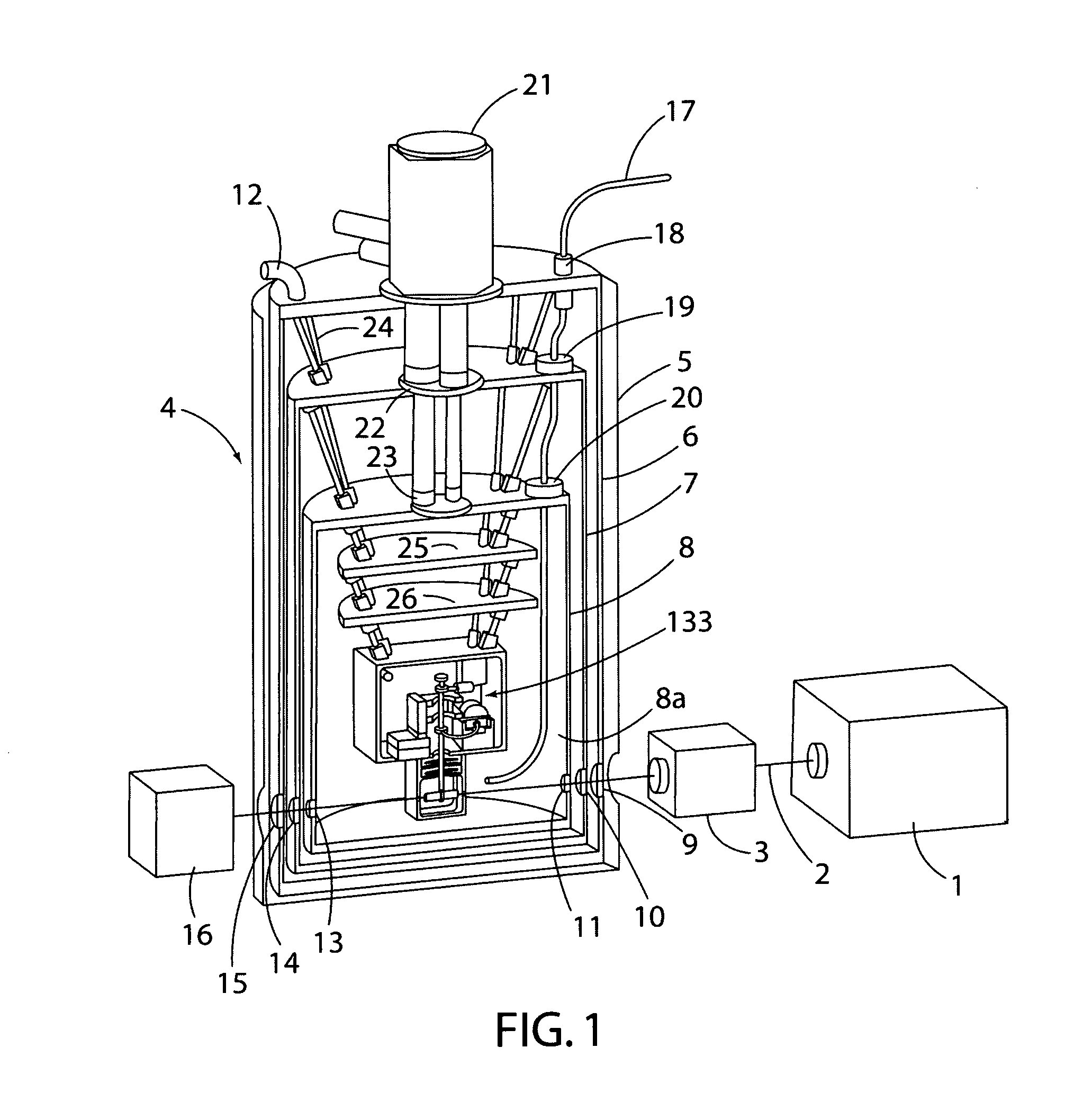
[0038]FIG. 1. shows the preferred embodiment of the present invention using a commercial mechanical refrigerator 21 as a source of refrigeration and windows as the principal means for the entry and exit of the beam of electromagnetic energy. No additional refrigeration stages are included in this simple cryostat, so the minimum temperature in the system is simply what the mechanical refrigerator can provide. The mechanical refrigerator 21 shown is a Cryomech PT-405, which is attached to a compressor (not shown) via two flexible metal hoses (also not shown). This refrigerator can achieve a base temperature below 3K.

[0039]The optical path is first described, referring to FIG. 1. Optical excitation sources include commercially available spectral lamp, pulsed or cw (continuous wave) laser, and white light laser. The excitation source 1 creates the excitation beam 2 of electromagnetic energy which passes through any required optical processing such as a monochromator 3 before entering th...


PUM


Abstract

An optical absorption calorimeter performs absorbance measurements at low cryogenic temperatures, such as above 0K to 5K (e.g. near liquid helium temperature), using high-resolution thermometry with SQUID readout to probe optical absorption to better than 1 ppb. This improved sensitivity yields improved performance in calorimetric absorption spectroscopy by lowering the required excitation power, improving the spectral resolution, and opening up the full spectrum, from near-IR to near-UV and beyond for analysis.

Description

[0001]This application claims benefits and priority of U.S. provisional patent applications Ser. No. 61 / 462,095 filed, Jan. 28, 2011, the entire disclosure of which is incorporated herein by reference.FIELD OF THE INVENTION[0002]The present invention relates to optical absorption calorimetry and, more particularly, to an optical absorption meter and method based on calorimetry employing temperature sensors with SQUID read-out device operating at low cryogenic temperatures in a manner to improve the sensitivity of optical loss measurements by several orders of magnitude.BACKGROUND OF THE INVENTION[0003]Many areas in science and technology require materials of the utmost purity and quality. In optics and photonics, wide-gap dielectric materials are particularly important as bulk materials for substrates, nonlinear optical elements, and optical coatings. In optical materials, operational limitations are often determined by residual absorption due to defects in the materials. In high po...

Claims


Application Information

Patent Timeline
IPC IPC(8): G01K17/00G01K7/36
CPCG01K7/36G01K2203/00G01K17/00G01K13/006
Inventor BOYD, STEPHEN THOMASRUDOLPH, WOLFGANG G.
Owner STC UNM
Learn More