
Electrical instrument, power management apparatus, power management system having the same, and method for controlling the same

a technology of power management system and power management apparatus, applied in non-electric variable control, process and machine control, instruments, etc., can solve the problems of inability to efficiently execute the functions of users of conventional electrical instruments to which dr is applied, and the cost of constructing an additional power plant for peak load is extremely high. , to achieve the effect of reducing inconvenience of us

Active Publication Date: 2012-08-02
SAMSUNG ELECTRONICS CO LTD
View PDF8 Cites 13 Cited by
  • Summary
  • Abstract
  • Description
  • Claims
  • Application Information

AI Technical Summary

Benefits of technology

[0032]The controller may continuously lower an operation level of an electrical instrument having a second lowest priority until the power consumption amount becomes less than the predetermined power amount when the power consumption amount exceeds the predetermined power amount even in a state in which the operation level of the electrical instrument having the lowest priority has been adjusted to a lowest operation level.
[0094]Moreover, the power amount consumed by the electrical instrument can be controlled by executing operation algorithms differentiated according to power rate information to thereby maximize energy efficiency at the user side.

Problems solved by technology

Costs for constructing an additional power plant for peak load are extremely high and maintenance costs for power plants constructed to maintain peak load for a short period are considerable.
However, conventional electrical instruments to which DR is applied cannot efficiently execute functions that users desire because they are powered on / off based on power rates.

Method used


Image

  • Electrical instrument, power management apparatus, power management system having the same, and method for controlling the same
  • Electrical instrument, power management apparatus, power management system having the same, and method for controlling the same
  • Electrical instrument, power management apparatus, power management system having the same, and method for controlling the same

Examples


Embodiment Construction

[0107]Reference will now be made in detail to the embodiments of the present invention, examples of which are illustrated in the accompanying drawings, wherein like reference numerals refer to like elements throughout.

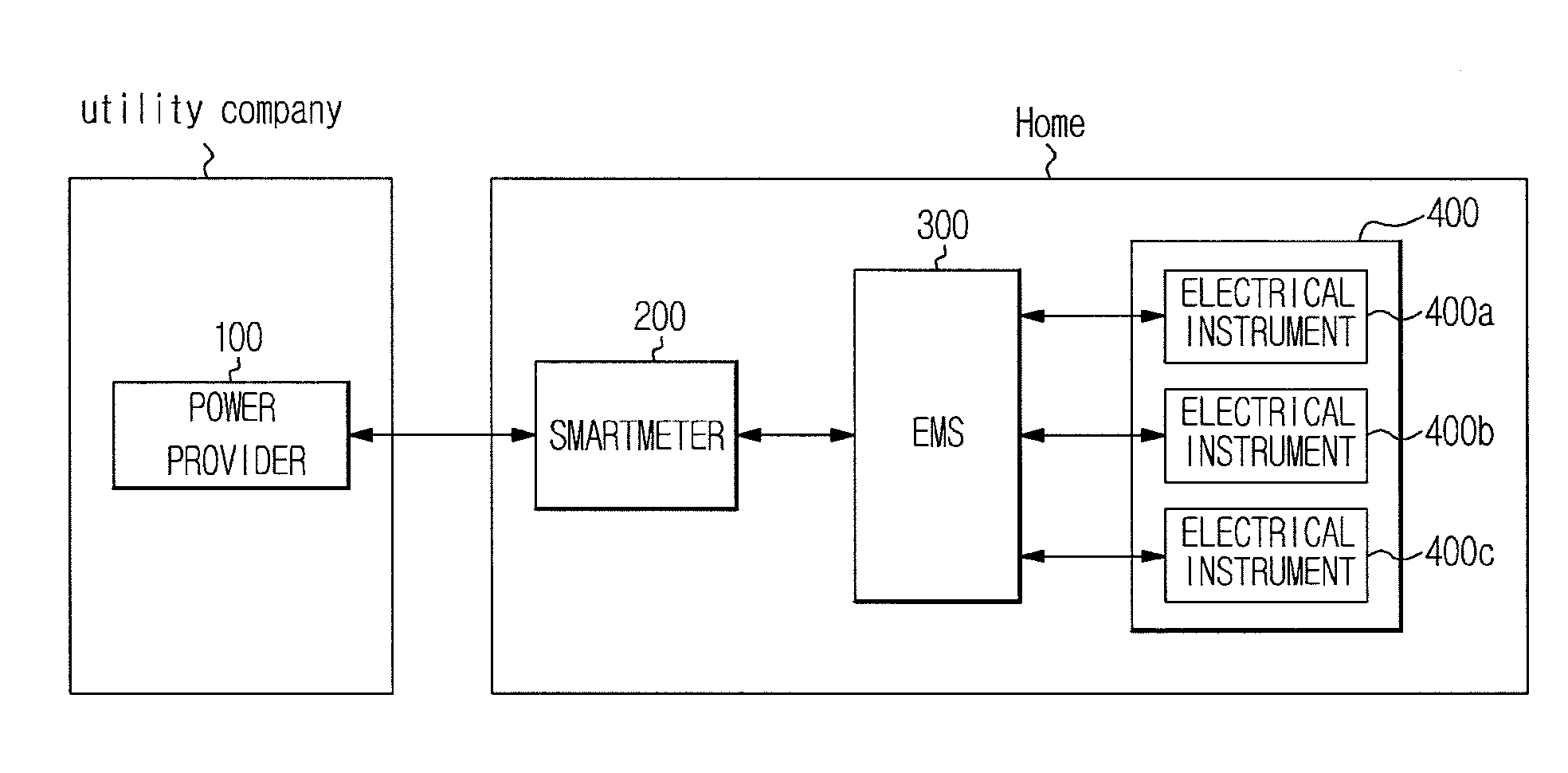
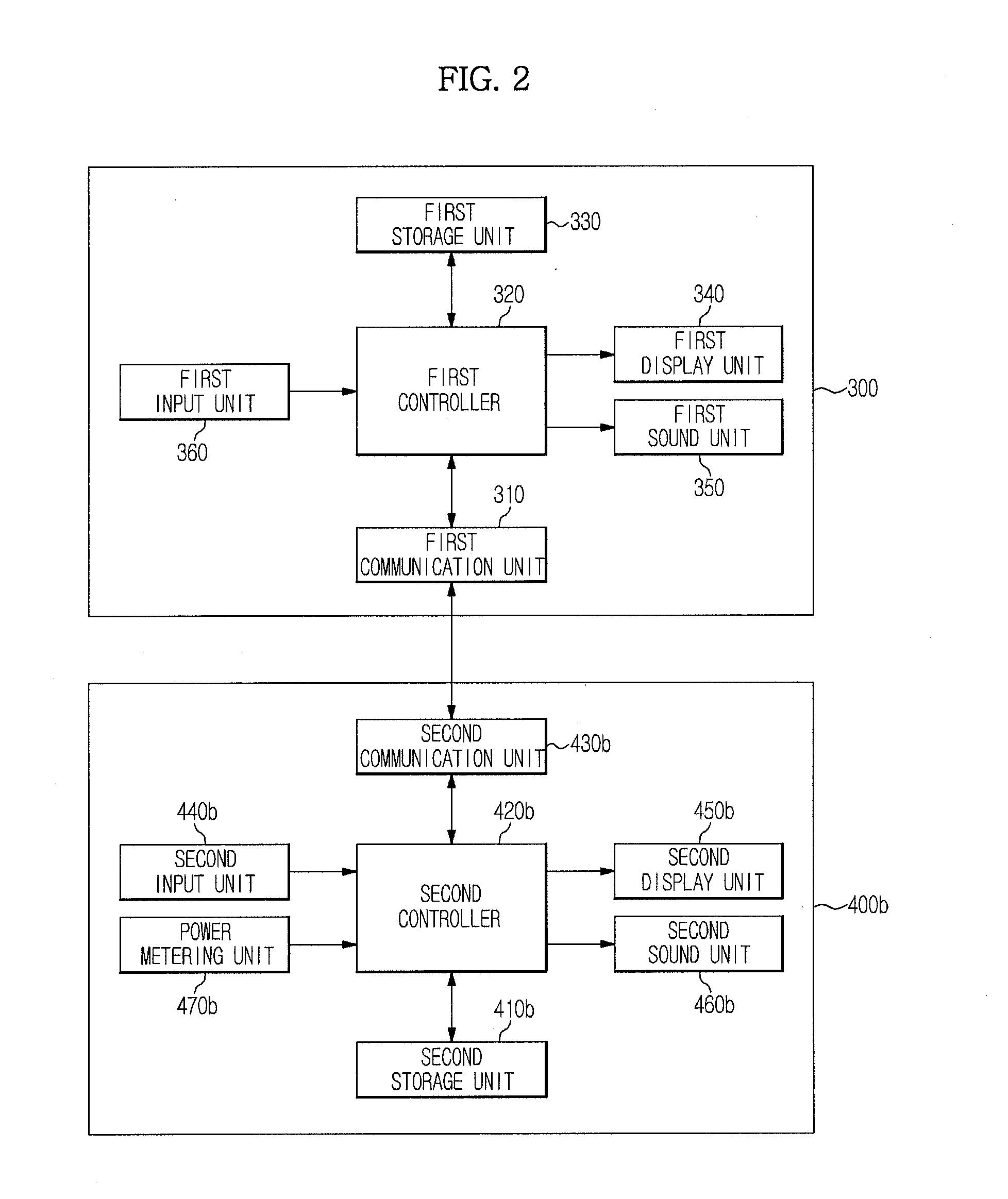
[0108]FIG. 1 is a block diagram of a power management system according to an embodiment of the present invention, and FIG. 2 is a block diagram of a power management apparatus and an electrical instrument included in the power management system according to an embodiment of the present invention.

[0109]Referring to FIG. 1, the power management system includes a power provider 100, a smartmeter 200, an energy management system (EMS) 300, and an electrical instrument 400 (400a, 400b and 400c).

[0110]The power provider 100 is a power supply source that is driven by a power supply company (utility company) so as to generate and provide power. The power provider 100 generates the power through atomic energy, hydroelectric power, thermoelectric power, wind power, etc., and pro...


PUM


Abstract

A power management system includes a plurality of electrical instruments and a power management apparatus. Each of the plurality of electrical instruments has at least one characteristic function and an arbitration function which is discriminated from the characteristic function and requires power arbitration. Each electrical instrument includes a plurality of operation algorithms having at least one characteristic function, operation levels respectively corresponding to the plurality of operation algorithms, power information for the respective operation levels, and power information of the arbitration function. The power management apparatus receives power rate information from a power provider, determines the operation levels of the plurality of electrical instruments and controls the electrical instruments to be driven at the determined operation levels. When an arbitration function selection signal is received from at least one of the electrical instruments while the electrical instruments are driven, the power management apparatus adjusts operation levels of other electrical instruments.

Description

CROSS-REFERENCE TO RELATED APPLICATIONS[0001]This application claims the priority benefit of Korean Patent Application No. 2011-0008375, filed on Jan. 27, 2011 in the Korean Intellectual Property Office, the disclosure of which is incorporated herein by reference.BACKGROUND[0002]1. Field[0003]Example embodiments of the following description relate to an electrical instrument, a power management apparatus, a power management system having the same, and a method for controlling the same to adjust power consumption, thereby balancing supply with demand of power.[0004]2. Description of the Related Art[0005]With the development of information and communication technologies, the number of devices powered by electricity is rapidly increasing, and thus, power demand increases year by year. In a power demand pattern, peak capacity is not reached during most days of the year, that is to say, power plants only operate at full capacity during a few days out of the year.[0006]A state in which a ...

Claims


Application Information

Patent Timeline
IPC IPC(8): G06F1/32
CPCG06Q10/063G06Q50/06H02J3/14H02J2003/143Y04S20/242Y02B70/3225Y02B70/3266Y04S20/222Y04S20/224H02J2003/146H02J2310/64H02J2310/14Y02B70/30Y04S50/10
Inventor JANG, JAE HWISHIN, JONG HYUNPARK, YOUNG JINPARK, HYUN SOO
Owner SAMSUNG ELECTRONICS CO LTD
Learn More