
Joint Arthroplasty Devices

a joint arthroplasty and joint technology, applied in the field of orthopaedic implants and systems, can solve the problems of high invasiveness of joint arthroplasties, loss of significant tissue and bone, loosening of implants,

Inactive Publication Date: 2012-08-02
CONFORMIS
View PDF5 Cites 115 Cited by
  • Summary
  • Abstract
  • Description
  • Claims
  • Application Information

AI Technical Summary

Benefits of technology

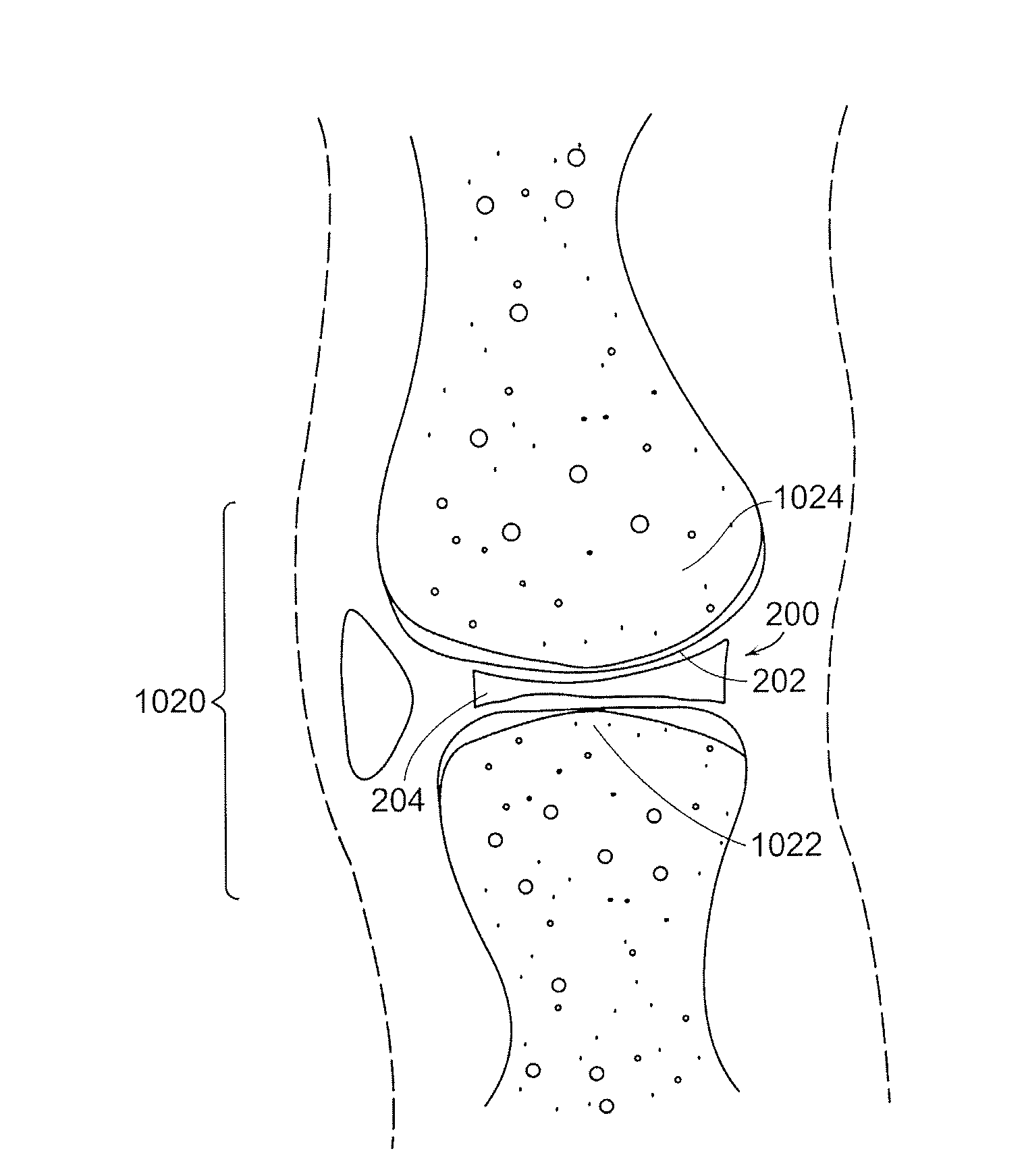
The patent describes a mobile bearing implant that includes a first component and a bearing component. The first component has a bone facing surface for engaging bone and cartilage, and an external surface. The bearing component has a first surface for slidingly engaging the external surface of the first component, and a second surface for engaging at least one of a second component, bone, and cartilage. The first component may be fixedly anchored into an articular surface using fins, keels, and / or pegs. The technical effects of this invention include improved bearing performance, reduced damage to the surrounding tissues, and improved stability of the implant.

Problems solved by technology

Implantation of these prosthetic devices is usually associated with loss of underlying tissue and bone and, with some devices, serious long-term complications associated with the loss of significant amount of tissue and bone can include infection, osteolysis and also loosening of the implant.
Such joint arthroplasties can be highly invasive and require surgical resection of the entire, or a majority of the, articular surface of one or more bones involved in the repair.
Reaming results in a loss of the patient's bone stock and over time subsequent osteolysis will frequently lead to loosening of the prosthesis.
Further, the area where the implant and the bone mate degrades over time requiring the prosthesis to eventually be replaced.
Since the patient's bone stock is limited, the number of possible replacement surgeries is also limited for joint arthroplasty.
In short, over the course of 15 to 20 years, and in some cases even shorter time periods, the patient can run out of therapeutic options ultimately resulting in a painful, non-functional joint.

Method used


Image

  • Joint Arthroplasty Devices
  • Joint Arthroplasty Devices
  • Joint Arthroplasty Devices

Examples


Embodiment Construction

[0049]The following description is presented to enable any person skilled in the art to make and use the invention. Various modifications to the embodiments described will be readily apparent to those skilled in the art, and the generic principles defined herein can be applied to other embodiments and applications without departing from the spirit and scope of the present invention as defined by the appended claims. Thus, the present invention is not intended to be limited to the embodiments shown, but is to be accorded the widest scope consistent with the principles and features disclosed herein. To the extent necessary to achieve a complete understanding of the invention disclosed, the specification and drawings of all issued patents, patent publications, and patent applications cited in this application are incorporated herein by reference.

[0050]As will be appreciated by those of skill in the art, methods recited herein may be carried out in any order of the recited events which ...


PUM

PropertyMeasurementUnit
timeaaaaaaaaaa
distanceaaaaaaaaaa
weightaaaaaaaaaa

Abstract

A mobile bearing implant includes a first component. The first component includes a bone facing surface for engaging one of a substantially uncut articular cartilage surface and a substantially uncut subchondral bone surface. The bone facing surface substantially matches the one of the articular cartilage surface and the subchondral bone surface. The mobile bearing implant further includes an external surface. A bearing component has a first surface for slidingly engaging the external surface of the first component, and a second surface for engaging at least one of a second component, bone, and cartilage.

Description

CROSS REFERENCE TO RELATED APPLICATIONS[0001]This application is a continuation of U.S. patent application Ser. No. 11 / 537,318, entitled “Joint Arthroplasty Devices,” filed Sep. 29, 2006, which in turn claims the benefit of U.S. provisional application 60 / 722,171, entitled “Patient Selectable Knee Joint Arthroplasty Devices,” filed Sep. 30, 2005.[0002]U.S. patent application Ser. No. 11 / 537,318 is also a continuation-in-part of U.S. patent application Ser. No. 10 / 997,407, entitled “Patient Selectable Knee Joint Arthroplasty Devices,” filed Nov. 24, 2004, which in turn is a continuation-in-part of U.S. patent application Ser. No. 10 / 752,438, entitled “Patient Selectable Knee Joint Arthroplasty Devices,” filed Jan. 5, 2004, which in turn is a continuation-in-part of U.S. patent application Ser. No. 10 / 724,010, entitled “Patient Selectable Joint Arthroplasty Devices and Surgical Tools Facilitating Increased Accuracy, Speed and Simplicity in Performing Total and Partial Joint Arthroplas...

Claims


Application Information

Patent Timeline
Patent Type & Authority Applications(United States)
IPC IPC(8): A61F2/30
CPCA61F2/30756A61F2310/00592A61F2/30942A61F2/38A61F2/3872A61F2/3877A61F2/4657A61F2002/30011A61F2002/30062A61F2002/30092A61F2002/30163A61F2002/30604A61F2002/30616A61F2002/30892A61F2002/30894A61F2002/30929A61F2002/30948A61F2002/3895A61F2210/0004A61F2210/0014A61F2230/0028A61F2250/0023A61F2310/00017A61F2310/00023A61F2310/00029A61F2310/00047A61F2310/00065A61F2310/00071A61F2310/00077A61F2310/00083A61F2310/00107A61F2310/00113A61F2310/00119A61F2310/00131A61F2310/00149A61F2310/00155A61F2310/00395A61F2/30767A61F2/3868A61F2002/30179
Inventor LANG, PHILIPPBURDULIS, JR., ALBERT G.FITZ, WOLFGANGSTEINES, DANIEL
Owner CONFORMIS
Learn More