Frequency modulation feedback system

Inactive Publication Date: 2012-08-02
HIWIN MIKROSYST
View PDF3 Cites 0 Cited by
  • Summary
  • Abstract
  • Description
  • Claims
  • Application Information

AI Technical Summary

Benefits of technology

[0011]It is therefore a primary object of the present invention to provide a frequency modulation feedback system, which is free from the interference of the voltage noise so that the reliability of the signal is enhanced and the problem of signal decay is overcome.
[0012]It is a further object of the present invention to provide the above frequency modulation feedback system, which can transmit the signal wirelessly to elongate signal transmission distance and facilitate use.

Problems solved by technology

In such wired signal transmission, the cable leads to increase of cost.
Moreover, the length of the cable will limit the site of use.
Under such circumstance, the intensity of the signal will inevitably decay with the increase of length or the signal will be interfered with by a noise 5.
1. The quality of the signal is affected due to decay of amplitude.
2. The transmission distance at most is only several tens of meters.
3. The conventional system is more sensitive to interference. Therefore, the conventional system is subject to interference of non-uniform addable voltage noise. In this case, the controller can hardly truly read the signal.

Method used


Image

  • Frequency modulation feedback system
  • Frequency modulation feedback system

Examples


Embodiment Construction

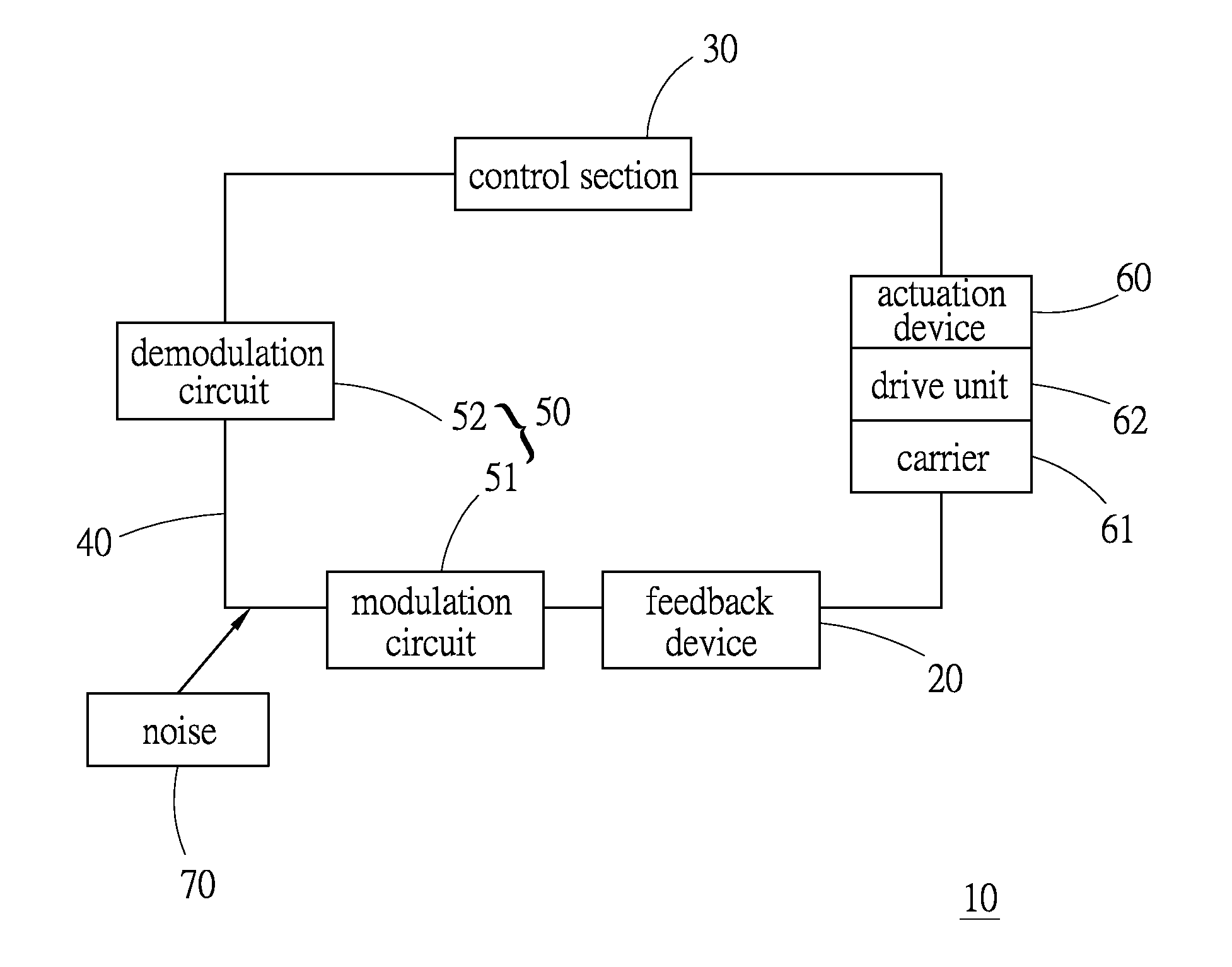
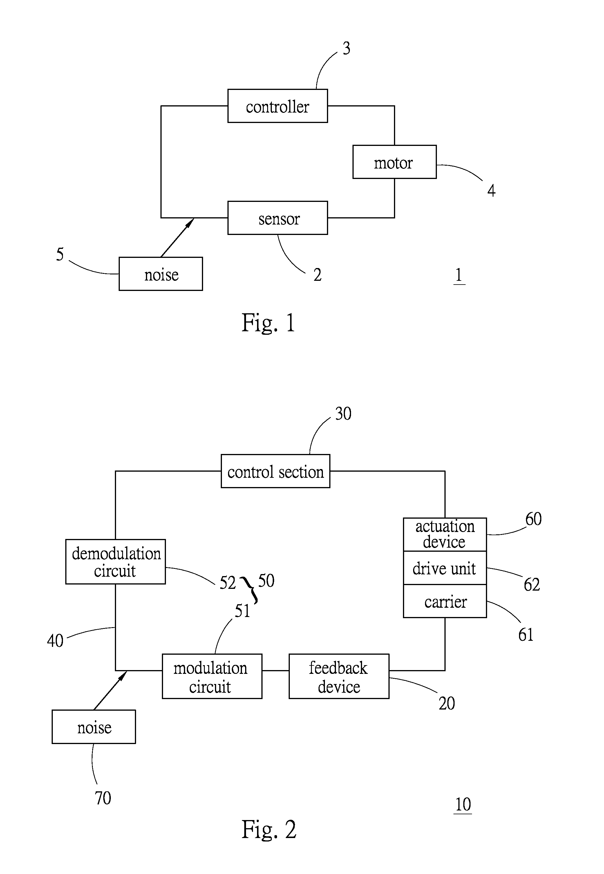
[0018]Please refer to FIG. 2. According to a preferred embodiment, the frequency modulation feedback system 10 of the present invention is applied to an actuation device 60. The actuation device 60 includes a carrier 61 slidably mounted on a slide rail and a drive unit 62 formed of a linear motor. The drive unit 62 is installed on the carrier 61 for driving the carrier 61 to linearly move along the slide rail. The actuation device 60 pertains to prior art and is not included in the scope of the present invention. Therefore, the actuation device 60 will not be further described hereinafter.

[0019]The frequency modulation feedback system 10 mainly includes a feedback device 20, a control section 30, a passage 40 and a modulation device 50.

[0020]The feedback device 20 serves to read a feedback signal of the carrier 61 and transmit the feedback signal.

[0021]The control section 30 serves to receive and read the feedback signal to drive the drive unit 62.

[0022]The feedback signal is transm...


PUM


Abstract

A frequency modulation feedback system applied to an actuation device composed of a carrier and a drive unit for driving the carrier. The frequency modulation feedback system includes: a feedback device for reading a feedback signal of the carrier and transmitting the feedback signal; a control section for receiving and reading the feedback signal to drive the drive unit; a passage, the feedback signal being transmitted from the feedback device via the passage to the control section; and a modulation device for modulating the waveform of the transmitted feedback signal. After the feedback device reads the feedback signal, the feedback device first transmits the feedback signal to the modulation device for the modulation device to change the waveform of the feedback signal. Then the feedback signal is transmitted via the passage to the control section for reading.

Description

BACKGROUND OF THE INVENTION[0001]1. Field of the Invention[0002]The present invention relates generally to a position feedback system, and more particularly to a frequency modulation feedback system.[0003]2. Description of the Related Art[0004]A linear motor is popularly applied to a tool machine. The linear motor via a drive unit drives the tool machine to linearly move along a slide rail. Following the advance of processing technique, it is often necessary to use high-precision measuring equipment for precisely locate the tool machine. In order to precisely linearly move the tool machine to a predetermined position, a position feedback system is often used to sense positional signals of a cooperative magnetic ruler for precisely driving and locating the tool machine.[0005]FIG. 1 shows a conventional position feedback system 1, which includes a sensor 2 and a controller 3. The position feedback system 1 works mainly in the principle that after the sensor 2 senses the signal, the se...

Claims


Application Information

Patent Timeline
IPC IPC(8): H03C3/00
CPCG05B19/19G05B2219/33186G05B2219/41365
Inventor LI, YU-MING
Owner HIWIN MIKROSYST
Why Eureka
Try Eureka