
Personal Load Distribution Device

Active Publication Date: 2012-08-02
LINEWEIGHT
View PDF25 Cites 32 Cited by
  • Summary
  • Abstract
  • Description
  • Claims
  • Application Information

AI Technical Summary

Benefits of technology

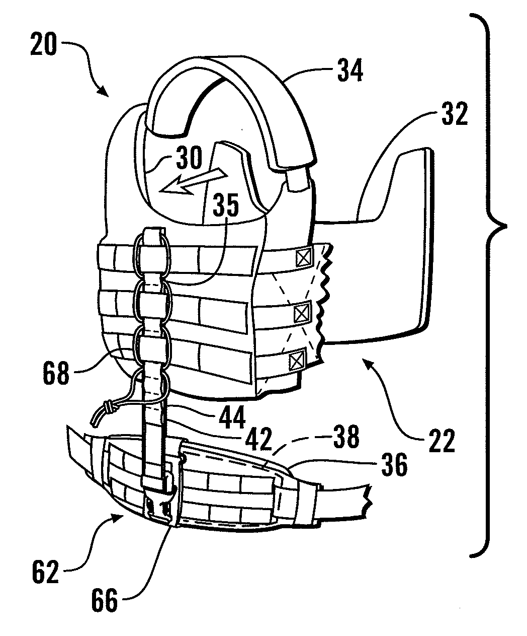
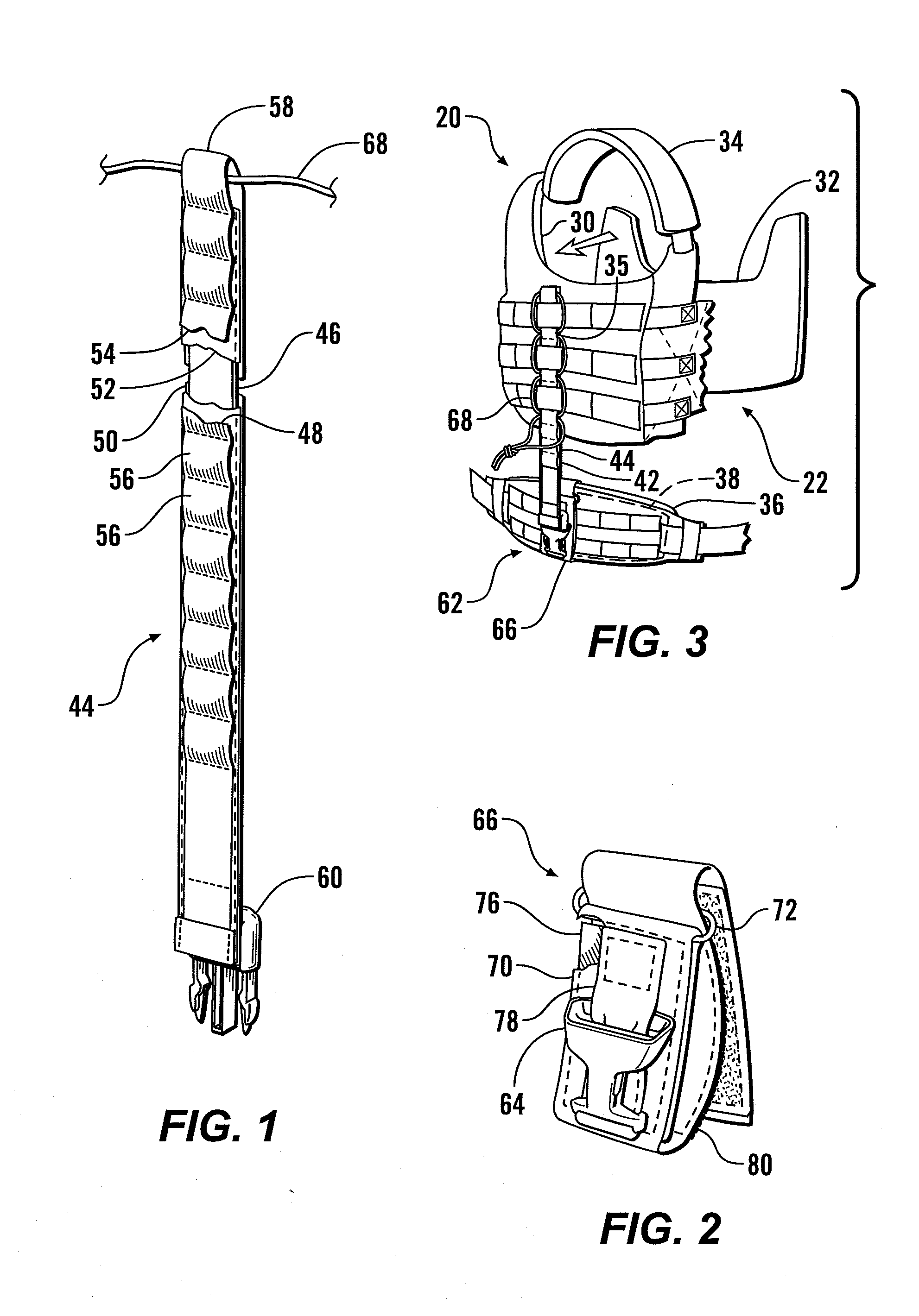
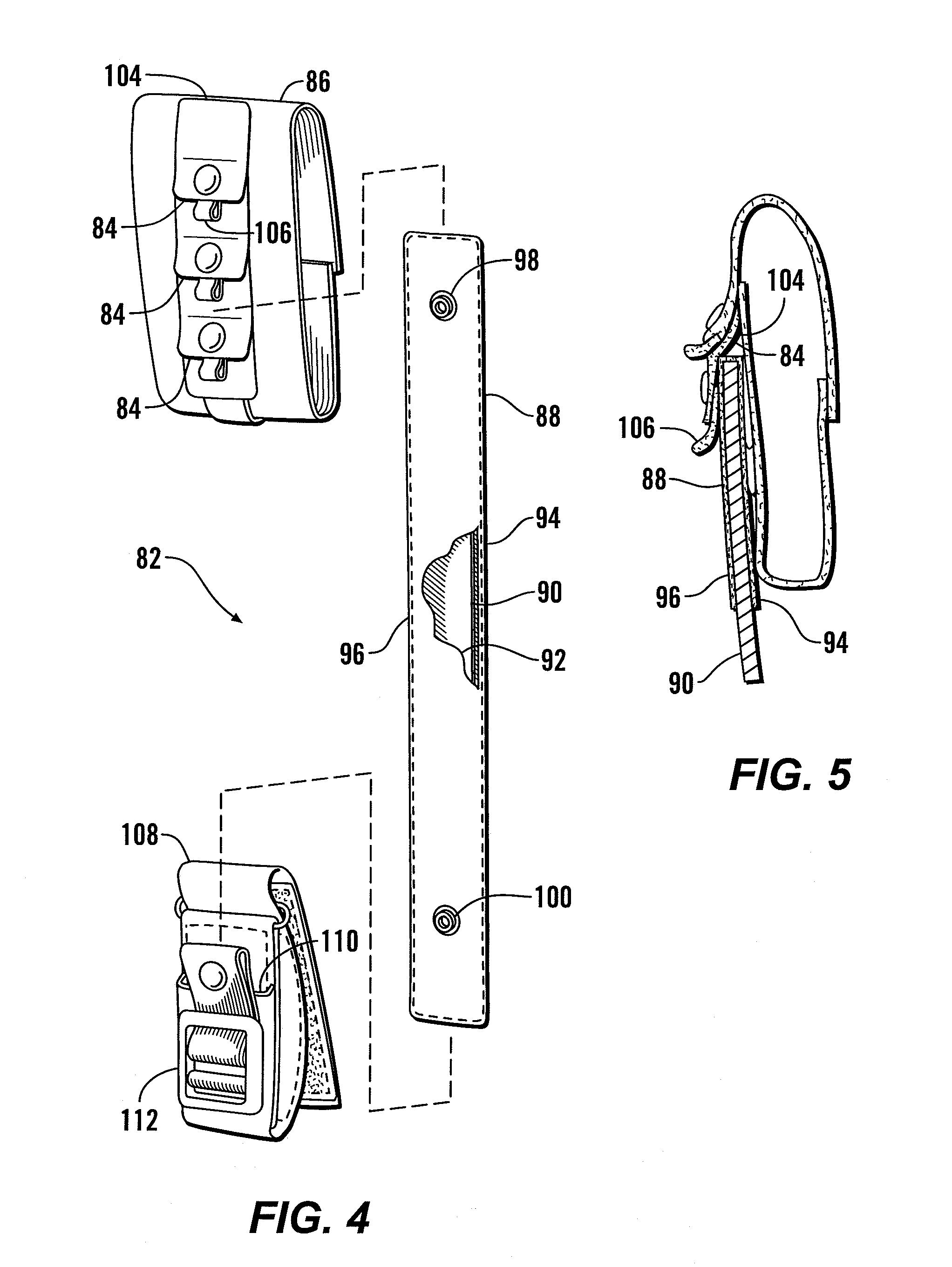
[0009]The load-carrying assembly of the present invention employs stiff bars to transfer the loads from a ballistic vest to a waist-encircling belt. Support assemblies are centered on each side of the wearer, and are flexibly connected to the vest and the belt, for example by engaging the PALS loops of the vest, and by a connection to a belt mount. When the wearer stands upright, with the belt properly tightened and at an appropriate height, the loads on the wearer's shoulders are transferred to the waist, relieving back stress. The attachment to the vest may be by the end of a bar being received within a downwardly opening pocket on the vest, or by a cord woven between the PALS loops on the vest and a series of horizontally-opening loops sewn to the stiff carbon fiber bars. Alternatively, various snap or buckle arrangements can be used where appropriate, or sidewardly projecting shelves may be fastened to the belt.
[0011]It is another object of the present invention to provide load transferring equipment for ballistic vests which is readily disconnected.

Problems solved by technology

Since protective armor vests are worn for long periods of time and during strenuous activity, this pressure on the shoulders and ultimately the spine is undesirable.
Morever, the prolonged strain of carrying these loads on the wearer's shoulders can reduce the wearer's effectiveness at whatever job he is performing, with increased metabolic cost, accelerated fatigue, and pain.

Method used


Image

  • Personal Load Distribution Device
  • Personal Load Distribution Device
  • Personal Load Distribution Device

Examples


Embodiment Construction

[0030]Referring more particularly to FIGS. 1-15, wherein like numbers refer to similar parts, a load carrying assembly 20 is shown in FIG. 3. The load carrying assembly 20 may include a conventional ballistic vest 22 such as the CAGE Armor Chassis™ manufactured by Crye Precision LLC of Brooklyn, N.Y., or the vest disclosed in U.S. application Ser. No. 11 / 972,528, entitled Configurable Body Armor, the disclosure of which is incorporated by reference herein. The vest 22, as shown in FIGS. 3 and 6 has a rear section 24 and a front section 26 spaced frontwardly of the rear section. The front and rear sections may include armor plates. A left side section 28 and a right side section 30 extend between the rear section 24 and the front section 26. The left and right side sections 28, 30 may each be provided with a side ballistic insert 32 comprised of multiple layers of ballistic fabric together with a molded plastic sheet formed into a continuous generally concave bent sheet element which...


PUM


Abstract

Support assemblies releasably extending between a ballistic vest and a waist encircling belt transfer the loads from the vest to the belt relieving the stress on the wearer's shoulders and spine. Each support assembly has a stiff carbon fiber bar enclosed within webbing which is attached to a side section of the vest such as by extending within a downwardly opening pocket, and is attached to the belt such as by an upwardly opening pocket. Alternatively, plastic shelves mounted to the belt can support the weight of the vest.

Description

CROSS REFERENCES TO RELATED APPLICATIONS[0001]This application claims the benefit of U.S. provisional App. No. 61 / 222,097, filed Jun. 30, 2009, the disclosure of which is incorporated by reference herein.STATEMENT AS TO RIGHTS TO INVENTIONS MADE UNDER FEDERALLY SPONSORED RESEARCH AND DEVELOPMENT[0002]Not applicable.BACKGROUND OF THE INVENTION[0003]The present invention relates to load-carrying supports in general, and more particularly to support systems which allow wearers to more adequately carry loads for extended periods.[0004]Soldiers and police officers, when in a position of harm from small arms, rifle fire, or shrapnel, can counter these hazards by wearing protective clothing. Ballistic armor vests and jackets can incorporate so-called “soft armor” for protection against low velocity projectiles such as handgun rounds, fragmentation rounds from a grenade or mortar, and miscellaneous shrapnel. Soft armor is composed of assemblies of ballistic fabric such as those formed from ...

Claims


Application Information

Patent Timeline
IPC IPC(8): A41D1/04
CPCA41D13/0007A41D2400/48A45F3/04F41H1/02A45F3/06A45F3/14A45F3/047A41D13/0012
Inventor CRYE, CALEB CLARK
Owner LINEWEIGHT
Learn More