Filter Drain Kit and Method

a filter and kit technology, applied in the direction of liquid handling, packaging goods, separation processes, etc., can solve the problems of inconvenient operation in confined spaces, increased oil leakage, and the same attachment of the containment boot, etc., and achieve the effect of small spa

Inactive Publication Date: 2012-07-26
BROADWAY THOMAS
View PDF17 Cites 5 Cited by
  • Summary
  • Abstract
  • Description
  • Claims
  • Application Information

AI Technical Summary

Benefits of technology

[0022]Yet another object of the present invention is to provide a new and improved filter drain device that is meant to be used within a small space.
[0023]Still anothe

Problems solved by technology

These devices have familiar design and structural elements for the purposes of removing oil filters and excess oil; however they are not conducive to functioning in confined spaces, removing oil from within the filter prior to removal or for storing the elements of the device in a convenient kit for further use.
Additional leakage of oil may occur with these additional steps.
Attachment of the containment boot has the same problems as when the draining occurs without the device, since the boot needs to be removed from a small space and leakage of oil may occur while removing.
Having to connect the coupler in a contained space underneath a car would be a struggle for anyone who has to use this device.
A special filter is required in order to use this device and issues still remain as to the removal of the oil and spill

Method used


Image

  • Filter Drain Kit and Method
  • Filter Drain Kit and Method
  • Filter Drain Kit and Method

Examples


Embodiment Construction

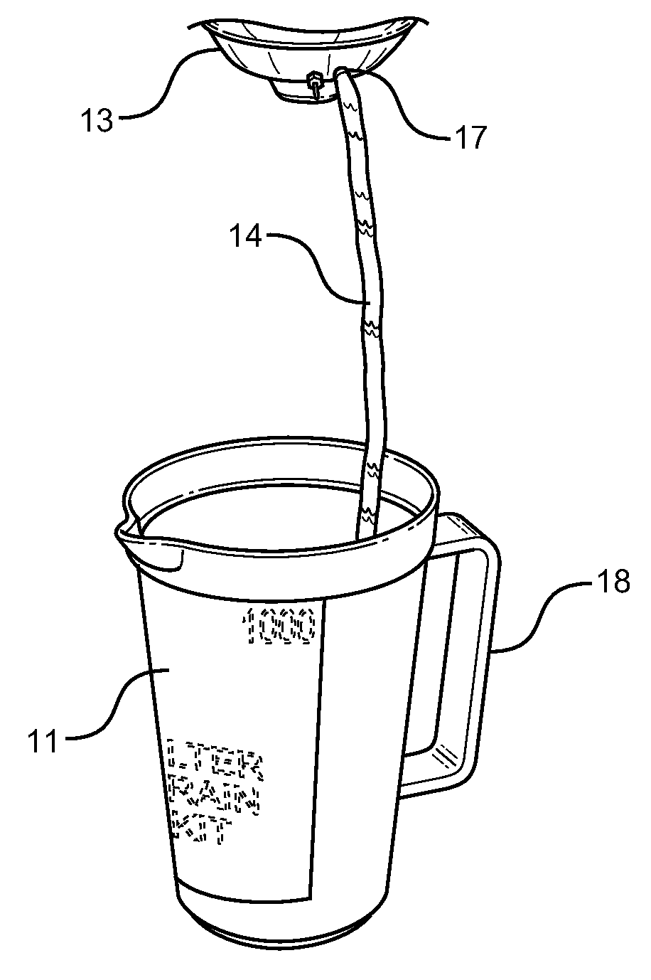
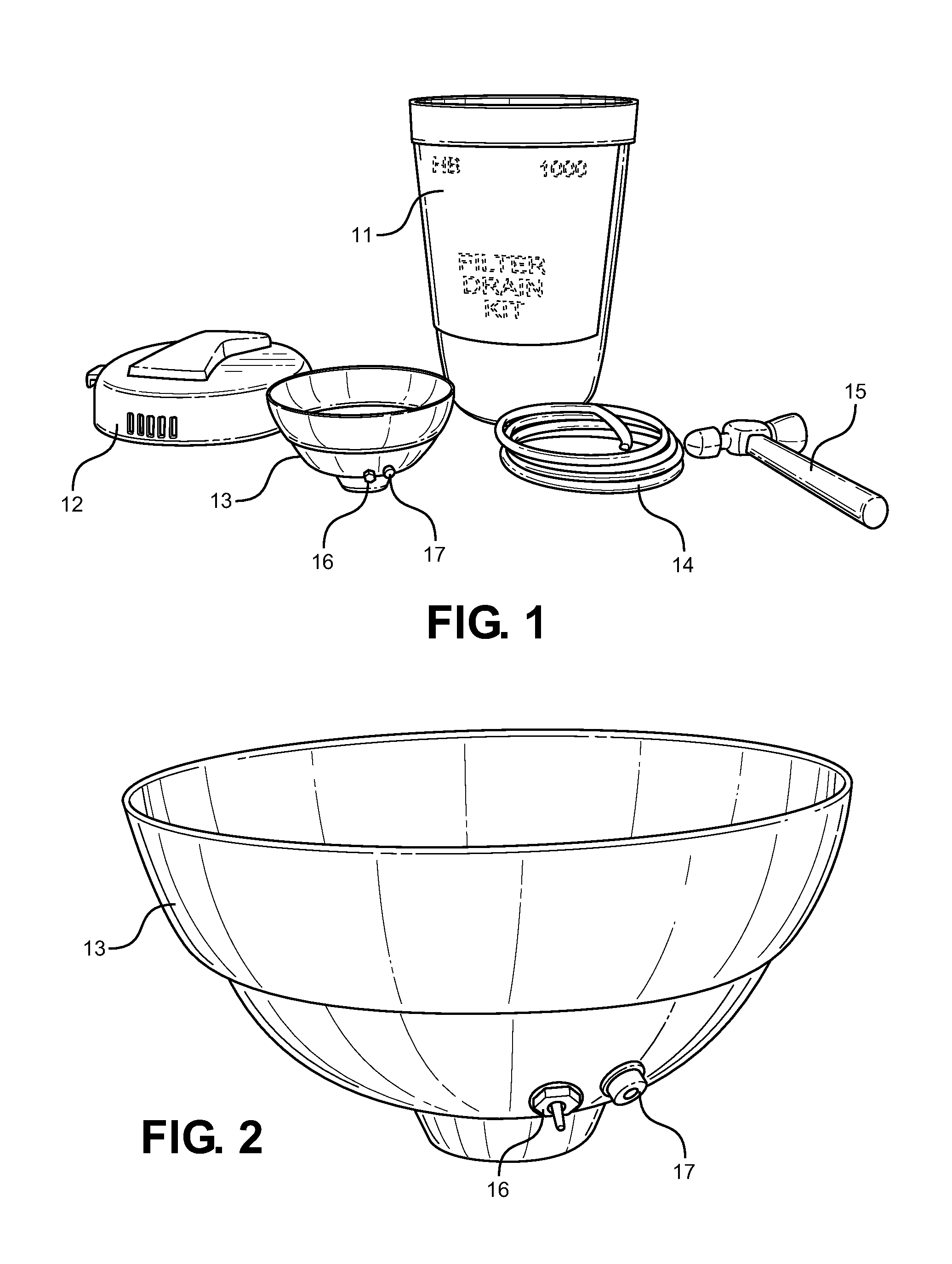
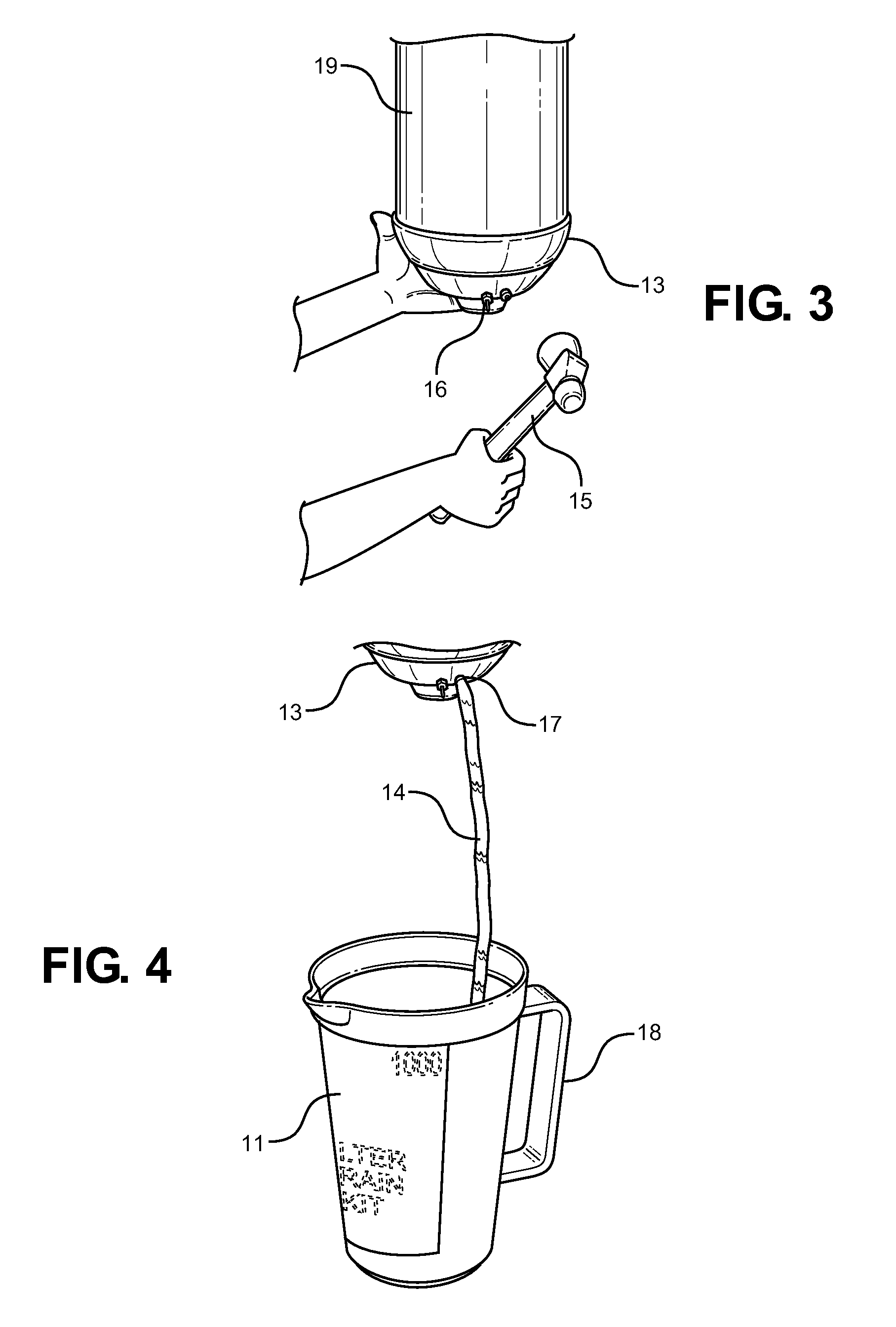
[0030]Referring now to FIG. 1, there is shown the filter drain kit 10 with all the components shown outside of the container 11. Shown is the cylindrical storage container 11, lid 12, flexible drain cup 13, hose 14, and hammer 15 or similar striking device. All items are contained in the storage container 11 when not in use. The flexible drain cup includes a puncture device 16 and drain fitting 17, while the storage container 11 includes a handle 18. The elements of the present invention, as shown in FIG. 1, comprise a kit that provides a user with a means to puncture the end of an oil filter, collect the draining motor oil therefrom without spillage and funnel the oil into a drain hose 14 and into a container 11 that eliminates splash back. The kit is self contained and can be stored together when not in use, and likewise be cleaned and reused for future oil changing operations.

[0031]Referring now to FIG. 2, there is shown a perspective view of the flexible drain cup 13 that is a p...


PUM

PropertyMeasurementUnit
Flexibilityaaaaaaaaaa
Circumferenceaaaaaaaaaa
Plasticityaaaaaaaaaa

Abstract

A filter drain kit device is provided having a cylindrical storage container with a lid and handle that holds a flexible drain cup. The cup includes a puncture device and drain fitting. The kit also includes a clear plastic drain hose to fit the drain fitting, and a striking hammer. The items within the kit allow for a method of removing oil from an oil filter without the spillage that normally accompanies this process. The components of the kit are meant to be wiped clean after use and placed back into the storage container, thereby allowing for reusability and ease of storage while not in use.

Description

CROSS REFERENCE TO RELATED APPLICATION[0001]This application claims the benefit of U.S. Provisional Application No. 61 / 435,839 filed on Jan. 25, 2011, entitled “Filter Drain Kit.”BACKGROUND OF THE INVENTION[0002]1. Field of the Invention[0003]The present invention relates to the field of engine oil filters, and more specifically to a method and apparatus for capturing and containing spillable oil during an oil filter removal operation.[0004]In 1955, Wix Corporation introduced the one piece “spin-on” disposable oil filter assembly. This assembly revolutionized the industry and soon became standard equipment on virtually every car and light truck. The filter includes a thin-wall, continuous outer container that houses and surrounds the paper or porous filter cartridge positioned thereabout. A spin-on assembly is mounted on the engine block and is held in place by compression against a deformable gasket.[0005]A popular design includes a flat-face O-ring type rubber gasket between the f...

Claims


Application Information

Patent Timeline
IPC IPC(8): B65B3/04
CPCF16N39/06B01D2201/24B01D35/31
Inventor BROADWAY, THOMAS
Owner BROADWAY THOMAS
Why Eureka
Try Eureka