
generator

a generator and generator technology, applied in the field of generators, can solve the problems of visual intrusion, safety concerns, bird and bat life destruction, serious disruption of airborne and ground based radar systems, etc., and achieve the effect of reducing the risk

Active Publication Date: 2012-07-12
THE POWER COLLECTIVE INC
View PDF13 Cites 14 Cited by
  • Summary
  • Abstract
  • Description
  • Claims
  • Application Information

AI Technical Summary

Benefits of technology

[0034]an isolation element between the first and second bracket sections to reduce the transfer of vibrations between the bracket sections.
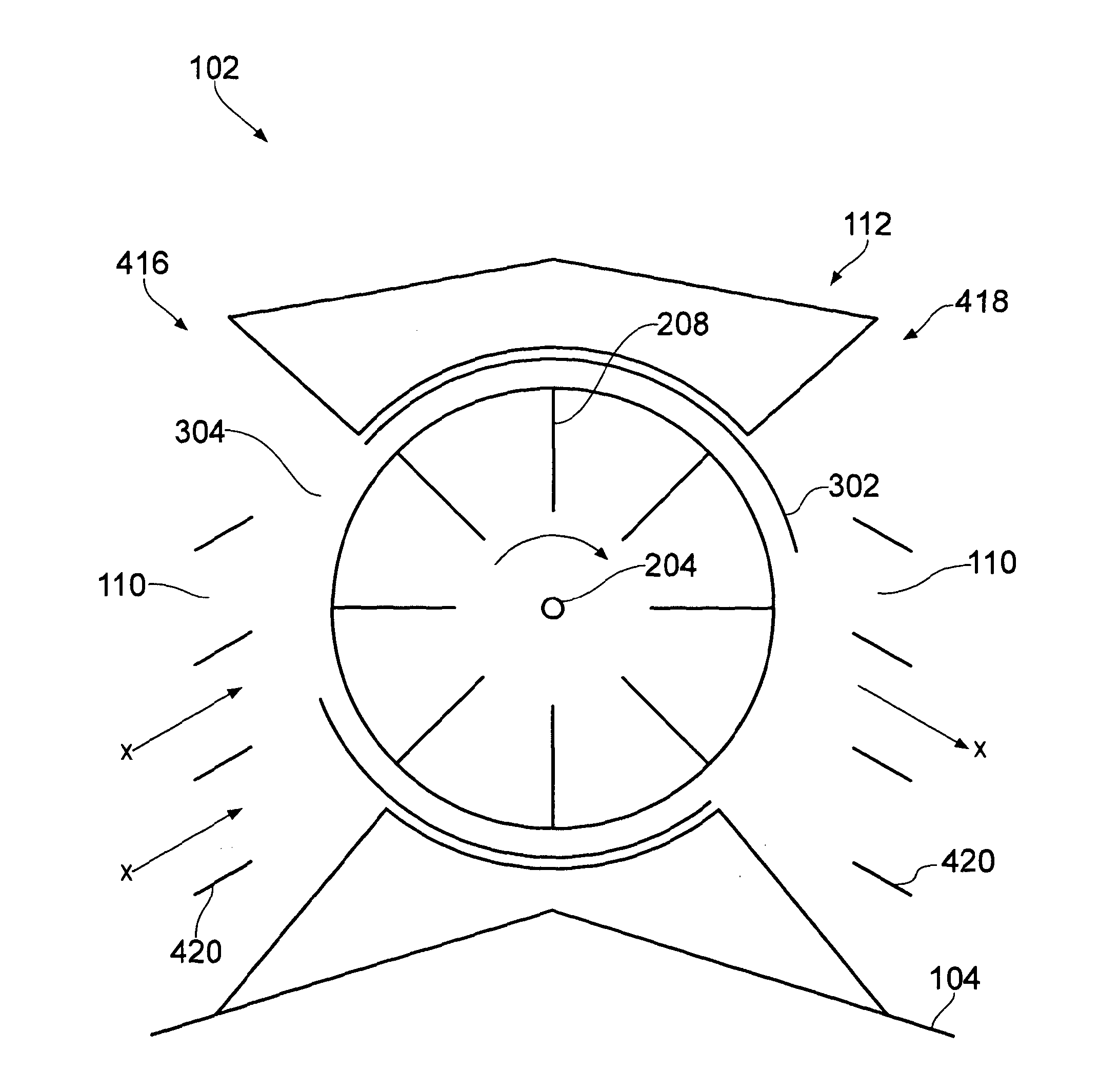
[0082]Advantageously, the wind allowed into the generator can be regulated by the flow regulation means, thus allowing the device to operate at acceptable levels of rotation depending on the ambient wind conditions. Accordingly, advantageously, the generator is operable to capitalise upon roof ridge increased airflow to produce useful power output at lower ambient wind speeds than conventional wind turbine designs and also to control the wind flow into the device thus alleviate the likelihood of mechanical failure at high wind speeds by operation of flow regulation means.

Problems solved by technology

HAWTs disadvantageously lead to visual intrusion, safety concerns, destruction of bird and bat life as well as serious disruption to airborne and ground based radar systems, due to both the large rotating surfaces and atmospheric disturbances behind the turbines.
Also, such HAWTs are exposed to the elements in all conditions, and accordingly are vulnerable to damage during extreme weather conditions.
Yet further, such HAWTs are typically grouped into “wind farms” in rural locations, remote from energy consumers leading to associated cost and inefficiencies in the distribution of the generated electricity.
Disadvantageously, the housing of JP200365206 provides only a limited protection to the rotors in the case of high wind, such that the wind turbine is vulnerable to damage in high winds.
Also in high winds the rotation of the rotor may be too high for the operational capacity of the power generation system.
Disadvantageously, the air flow guides are directly exposed to high winds and are susceptible to damage.
Disadvantageously, such a wind turbine is complex and expensive.
Further, the closable flaps remain directly exposed to high winds, and so are susceptible to damage.
Disadvantageously, the device of JP2006266236 is only capable of operating with the wind attenuator in an unattenuated orientation or an attenuated orientation.
Consequently, wind exposure of the rotor cannot be optimised to maximise energy generation.
Further, the rotor cannot be completely shielded from the wind in high wind conditions or during maintenance.
Such a mechanically operated mechanism is vulnerable to manufacturing tolerances, as well as mechanical wear over the operational lifetime.

Method used


Image

  • generator
  • generator
  • generator

Examples


Embodiment Construction

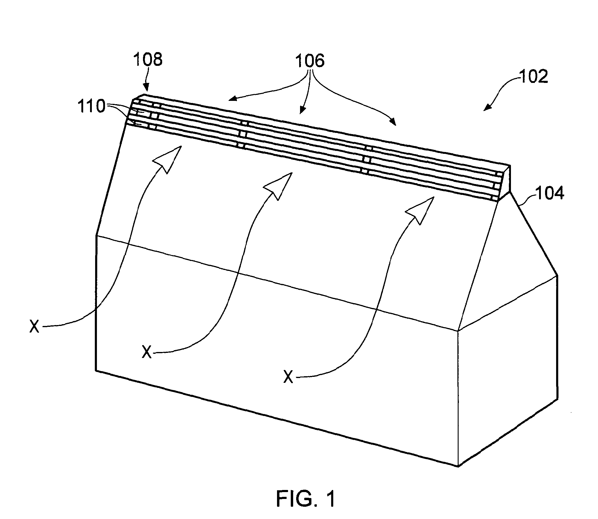
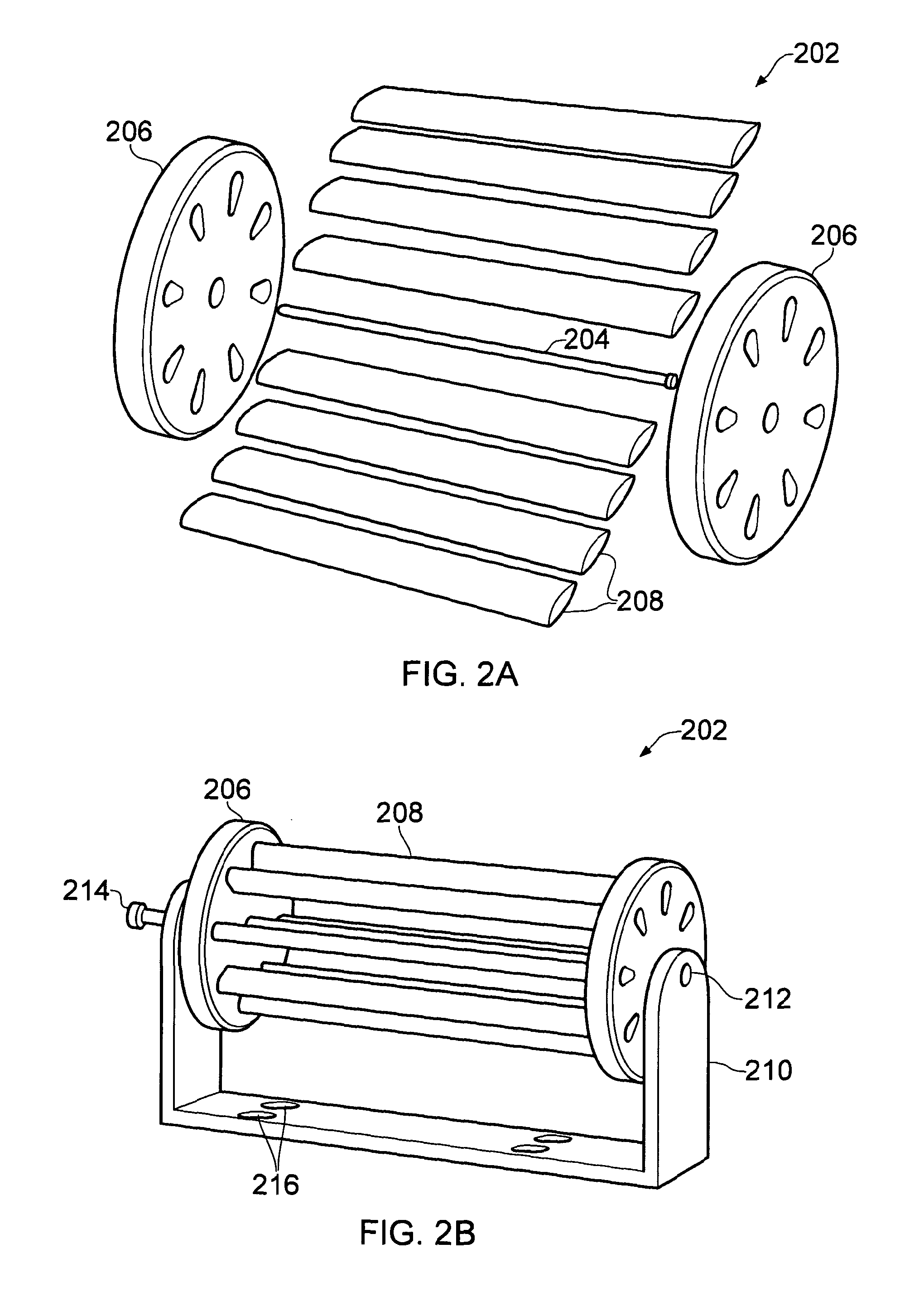
[0094]Referring first to FIG. 1 there is shown a schematic perspective view of a wind turbine assembly 102 secured to a pitched roof 104 comprising three modular wind turbine assembly sections 106 and an alternator section 108. As can be seen by curved arrows “X” wind is funnelled up the roof 104 toward the device 102 and through slot-like apertures 110 in the housing 112 toward the turbine assembly (described hereunder with regard to FIGS. 2 and 3).

[0095]Empirical measurement has shown that for a usual 30 degree to 45 degree pitched roof, incident wind is compressed as it clears the angled obstruction of the roof surface into a high speed flow band around the roof ridge, known as the Aeolian flow band. This band extends approximately 300 mm above the ridge top and 450 mm forward along the roof facing the incident wind. At this point, measured speeds may be of the order of three times that of the ambient wind speed.

[0096]Louvred slats in the housing pre-process and condition the inc...


PUM


Abstract

A wind turbine assembly comprising, an elongate generally cylindrical rotor operable to rotate about an axis, an elongate rotor housing that houses the rotor and which is adapted to be secured to a roof, and a flow regulator adapted to regulate wind flow to the rotor, wherein the flow regulator is orientatable in an open orientation, a closed orientation and a partially open orientation.

Description

FIELD OF INVENTION [0001]The present invention relates to a generator, specifically to a generator for generating electricity from wind power.BACKGROUND TO THE INVENTION [0002]The generation of electricity from wind power is well known in the art. However, although wind power is known to be one of the most valuable sources of renewable energy, it has been characterised by moderate to very large wind turbines, typically grouped together in “wind farms”. Well known are large scale Horizontal Axis Wind Turbines, or HAWTs, which are the familiar tower mounted propellers, with a rear mounted alternator, and which can be as high as several hundred feet tall and hundreds of feet in diameter. Other less common designs of large-scale wind turbine comprise Savonius rotors or Darrieus rotors, as described in U.S. Pat. No. 1,697,574 and U.S. Pat. 1,835,018 respectively.[0003]HAWTs disadvantageously lead to visual intrusion, safety concerns, destruction of bird and bat life as well as serious di...

Claims


Application Information

Patent Timeline
Patent Type & Authority Applications(United States)
IPC IPC(8): H02P9/04F03D5/00F03D9/00
CPCF03D3/002F03D3/0418F03D11/04F05B2240/911Y02E10/74F05B2260/96Y02B10/20Y02B10/30Y02E10/728F05B2240/9112F03D13/20F03D9/34F03D9/25E04D3/40F03D3/0427F16F1/36F05B2240/2212F05B2240/217F05B2270/304
Inventor KEECH, WINSTON DONALD
Owner THE POWER COLLECTIVE INC
Learn More