Vehicle seat
a technology for vehicles and seats, applied in the field of vehicles, can solve the problems of occupants' thighs affecting the steering wheel or other such components, burdening an aged person or other such persons, etc., and achieve the effect of easy entry and exit of the vehicl
- Summary
- Abstract
- Description
- Claims
- Application Information
AI Technical Summary
Benefits of technology
Problems solved by technology
Method used
Image


Examples
embodiment 1
[0084]In the following, a vehicle seat according to Embodiment 1 of the present invention will be illustrated with reference to FIGS. 1(A) to 7.
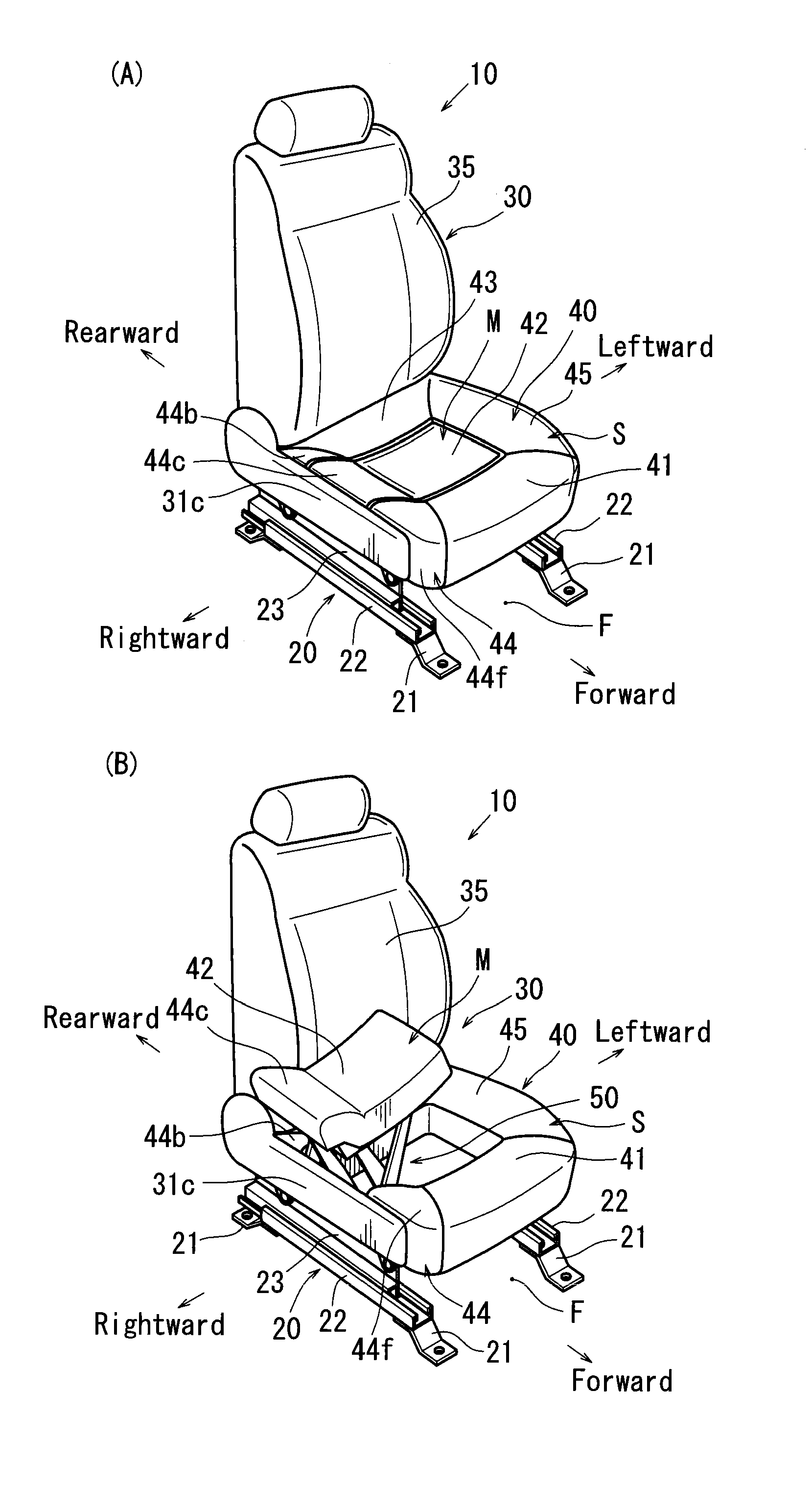
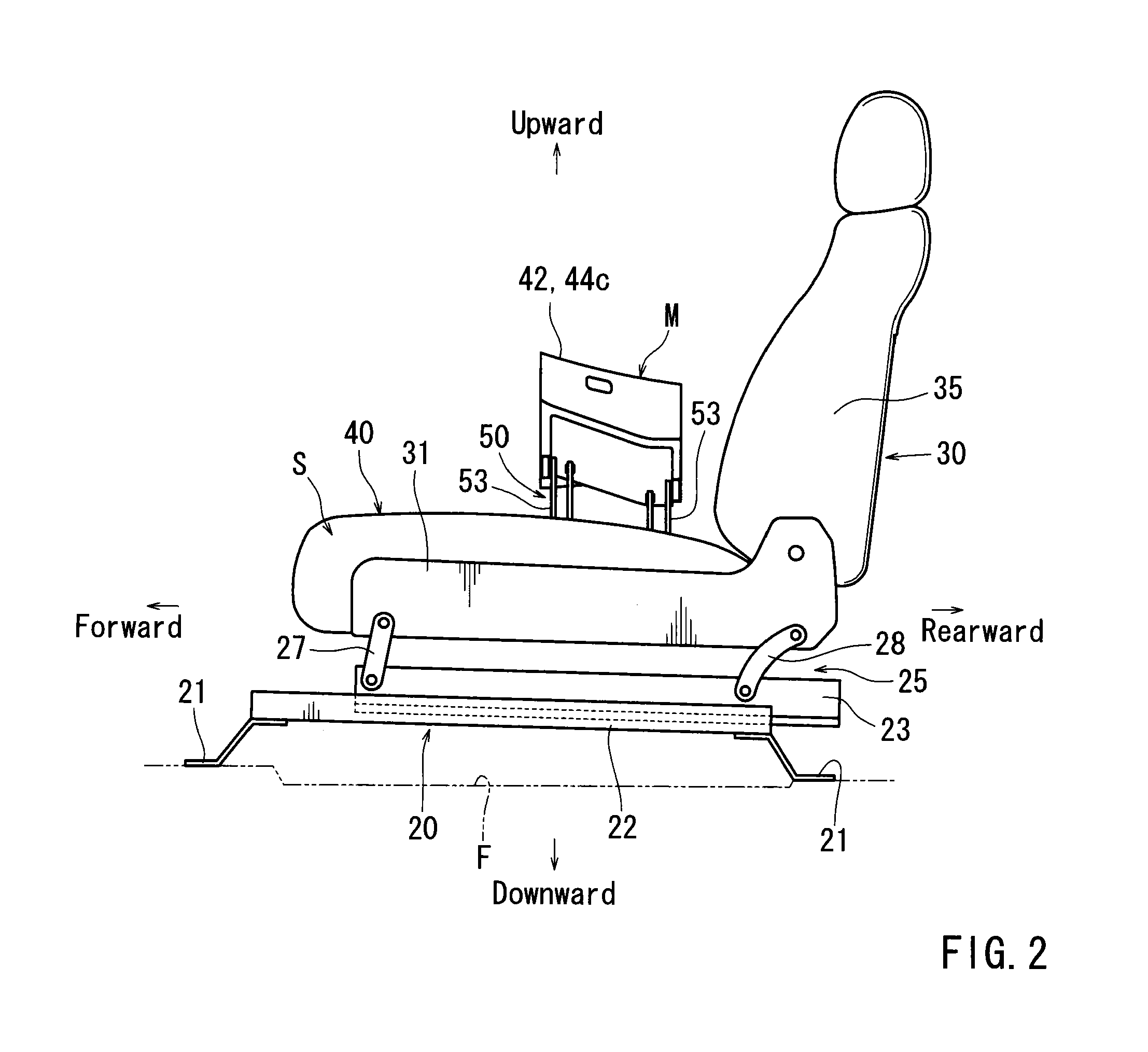
[0085]Further, forward and rearward, rightward and leftward, and upward and downward in the drawings respectively correspond to forward and rearward, rightward and leftward, and upward and downward of a vehicle seat and a passenger vehicle having the vehicle seat. Further, forward and rearward, rightward and leftward, and upward and downward referred to in the specification also correspond to forward and rearward, rightward and leftward, and upward and downward as defined above.
10>
[0086]A vehicle seat 10 according to the present embodiment is a seat (driver's seat or other such seats) of the vehicle having a relatively low vehicle height, which seat is constructed to allow an occupant to sit thereon from right passing through a right door opening.
[0087]As shown in FIGS. 1(A), 1(B) and 2, the vehicle seat 10 has a seat main body 30, a longitu...
embodiment 2
[0130]In the following, a vehicle seat according to Embodiment 2 of the present invention will be described with reference to FIGS. 8 to 14.
[0131]In a conventional vehicle seat (Japanese Laid-Open Patent Publication No. 7-69106), a movable seat portion positioned in a center of a seat cushion is vertically rotatable about a front end side thereof. Further, a rear portion of the movable seat portion can be pushed up by a drive mechanism and a drive arm that are disposed below the seat cushion. That is, when the rear portion of the movable seat portion is pushed up by the drive mechanism and the drive arm, the movable seat portion rotates upwardly about the front end side thereof, so that a buttock receiving portion supporting the buttocks of an occupant can be raised.
[0132]The drive mechanism has a feed screw portion that is vertically positioned, a nut portion that is threadably engaged with the feed screw portion, and a motor that is configured to rotate the feed screw portion abou...
embodiment 3
[0181]In the following, a vehicle seat according to Embodiment 3 of the present invention will be described with reference to FIGS. 15 to 24.
[0182]As shown in FIG. 33, a conventional vehicle seat (Japanese Laid-Open Patent Publication No. 2007-237804) has a seat cushion 600 that is composed of a cushion front portion 602 and a cushion rear portion 603. A front end lower portion of the cushion front portion 602 is connected to a front end portion of a seat frame 606 via a hinge 605. Conversely, a rear end lower portion of the cushion front portion 602 is connected to a front end lower portion of the cushion rear portion 603 via a hinge 607. Further, the cushion rear portion 603 is supported by a damper 608 from below. As a result, when an occupant sits on the cushion rear portion 603 and the cushion front portion 602 pushed up by the damper 608 in order to get in a vehicle, the cushion rear portion 603 and the cushion front portion 602 can be gently lowered to a sitting position agai...
PUM
 Abstract
Description
Claims
Application Information
 - R&D
- Intellectual Property
- Life Sciences
- Materials
- Tech Scout
- Unparalleled Data Quality
- Higher Quality Content
- 60% Fewer Hallucinations
Browse by: Latest US Patents, China's latest patents, Technical Efficacy Thesaurus, Application Domain, Technology Topic, Popular Technical Reports.
© 2025 PatSnap. All rights reserved.Legal|Privacy policy|Modern Slavery Act Transparency Statement|Sitemap|About US| Contact US: help@patsnap.com