Eureka AIR delivers breakthrough ideas for toughest innovation challenges, trusted by R&D personnel around the world.

Cable fixing bracket and manufacturing method thereof

a technology for fixing brackets and cables, which is applied in the direction of machine supports, manufacturing tools, shock absorbers, etc., can solve the problems of poor welding, increased production costs and manufacturing time of brackets, and peeling of the sheath of cables, so as to improve productivity, reduce production costs, and simplify the manufacturing process

Active Publication Date: 2012-07-05
DASUNG
View PDF9 Cites 1 Cited by
  • Summary
  • Abstract
  • Description
  • Claims
  • Application Information

AI Technical Summary

Benefits of technology

[0007]The present invention has been made in an effort to provide a cable fixing bracket having advantages of simplifying manufacturing process, reducing manufacturing cost, and improving productivity by integrally manufacturing the bracket in a single process.
[0008]In addition, the present invention has been made in an effort to provide a cable fixing bracket having further advantages of reducing assembly process and inferiority rate by eliminating welding process for assembling various parts.
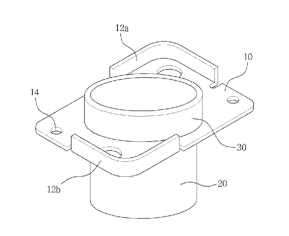
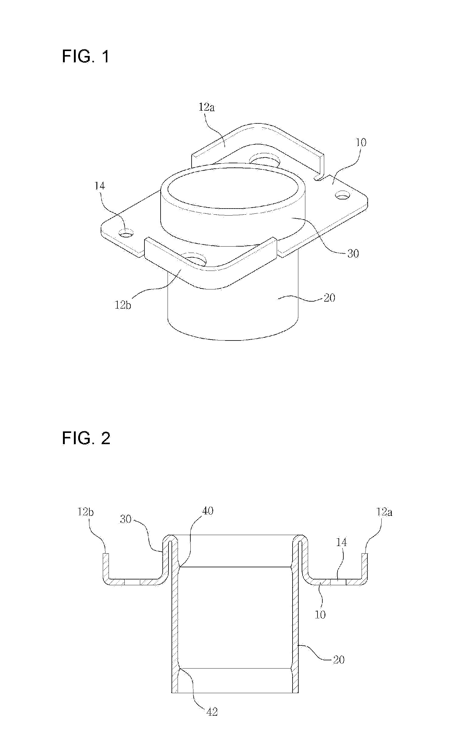
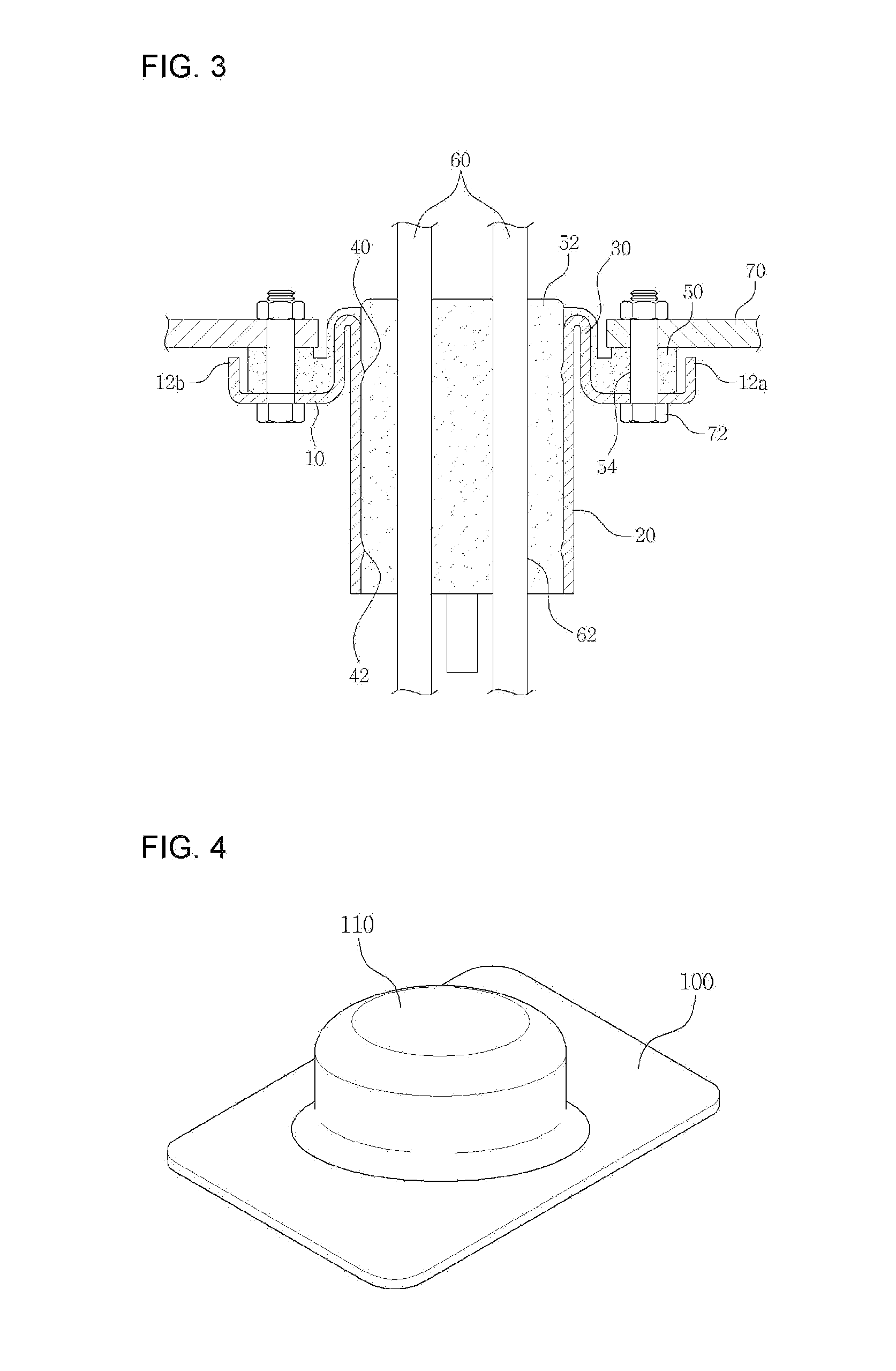
[0009]A cable fixing bracket according to an exemplary embodiment of the present invention includes a fixed section adapted to be fixed to a supporting body by forming at least one of engaging holes thereon and having a surface on which a first vibration-isolating member for reducing vibration is positioned, a connection section protruded from the surface of the fixed section to a first direction, and a cable supporting section extending from an end of the connection section to a second direction opposite to the first direction, and have an inside adapted to be filled with a vibration-isolating member supporting a cable. A partition is protruded perpendicularly to a plane of the fixed section from an edge portion of the fixed section. At this time, the fixed section, the connection section, and the cable supporting section are integrally formed with each other by pressing a single metal plate. Therefore, manufacturing is facilitated.

Problems solved by technology

The cables have problems that a sheath of the cable peels off by being rubbed against a vehicle body due to vibration of the vehicle or cables are entangled with each other.
However, since the fixing plate and the cable supporting body are assembled through welding after being manufactured separately, production cost and manufacturing time of the bracket may increase.
At this time, poor welding may occur and inferiority rate may be increased.

Method used


Image

  • Cable fixing bracket and manufacturing method thereof
  • Cable fixing bracket and manufacturing method thereof
  • Cable fixing bracket and manufacturing method thereof

Examples


Embodiment Construction

[0023]The present invention will be described more fully hereinafter with reference to the accompanying drawings, in which exemplary embodiments of the invention are shown. The present invention, however, can be realized by various embodiments and is not limited to the exemplary embodiment explained herein. Similar elements in the specification are denoted by the same reference numeral.

[0024]Referring to FIG. 1 to FIG. 3, a cable fixing bracket according to an exemplary embodiment of the present invention will be described in detail.

[0025]FIG. 1 is a perspective view for showing a part of a cable fixing bracket according to an exemplary embodiment of the present invention, FIG. 2 is a cross-sectional view of an exemplary embodiment shown in FIG. 1, and FIG. 3 is a cross-sectional view for showing use of a cable fixing bracket according to an exemplary embodiment of the present invention.

[0026]Referring to FIG. 1 and FIG. 2, the cable fixing bracket according to the present exemplary...


PUM

PropertyMeasurementUnit
lengthaaaaaaaaaa
circumferenceaaaaaaaaaa
cylindrical shapeaaaaaaaaaa

Abstract

A cable fixing bracket includes: a fixed section fixed to a supporting body; a connection section integrally extended from one surface of the fixed section; and a cable supporting section folded from the end section of the connection section to be integrally extended towards the other surface of the fixed section and supporting a cable. The cable fixing bracket is manufactured integrally in a single process, thereby simplifying the manufacturing process, reducing the manufacturing cost and improving productivity.

Description

BACKGROUND OF THE INVENTION[0001]The present invention relates to a cable fixing bracket that fixes a cable to a structure and to a method for manufacturing the cable fixing bracket.[0002]A cable is provided with a wire for plugging in or power delivery and is used for delivering electricity or driving torque. The cables used in a vehicle, for example, are a parking brake cable, a hood open switch cable, a trunk open switch cable, a transmission control cable of an AT vehicle, and so on.[0003]The cables have problems that a sheath of the cable peels off by being rubbed against a vehicle body due to vibration of the vehicle or cables are entangled with each other. For preventing such problems, the cables are fixed to the vehicle body through a bracket. In addition, a vibration-isolating member is provided at the bracket so as to prevent vibration of the vehicle body from being transmitted to the cable.[0004]After a fixing plate fixed to the vehicle body by a bolt and a cable supporti...

Claims


Application Information

Patent Timeline
Patent Type & Authority Applications(United States)
IPC IPC(8): F16L55/035B23P11/00F16F7/00
CPCH02G3/083Y10T29/49826H02G3/22
Inventor MOON, SEUNG
Owner DASUNG
Why Eureka
Eureka Blog
Learn More